Low Ohmic Shunt:
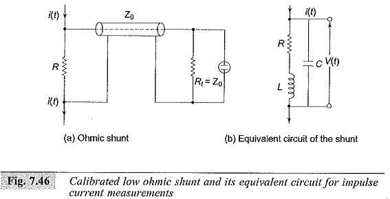
The most common method employed for high impulse current measurements is a Low Ohmic Shunt shown in Fig. 7.46. The equivalent circuit is shown in Fig. 7.46b. The current through the resistive element R produces a voltage drop V(t) = i (t)R. The voltage signal generated is transmitted to a CRO through a coaxial cable of surge impedance Z0. The cable at the oscilloscope end is terminated by a resistance Ri = Z0 to avoid reflections.
The resistance element, because of its large dimensions will have a residual inductance L and a terminal capacitance C. The inductance L may be neglected at low frequencies ω but becomes appreciable at higher frequencies (ω) when ωL is of the order of R. Similarly, the value of C has to be considered when the reactance 1/ωC is of comparable values. Normally L and C become significant above a frequency of 1 MHz. The resistance value usually ranges from 10 μΩ to few milliohms, and the voltage drop is usually about a few volts. The value of the resistance is determined by the thermal capacity and heat dissipation of the Low Ohmic Shunt.
The voltage drop across the Low Ohmic Shunt in the complex frequency domain may be written as:
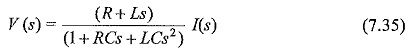
where s is the complex frequency or Laplace transform operator and V(s) and I(s) are the transformed quantities of the signals v(t) and i(t). With the value of C neglected it may be approximated as:
![]()
It may be noted here that the stray inductance and capacitance should be made as small as possible for better frequency response of theLow Ohmic Shunt. The resistance shunt is usually designed in the following manner to reduce the stray effects.
- Bifilar flat strip design,
- coaxial tube or Park’s shunt design, and
- coaxial squirrel cage design.
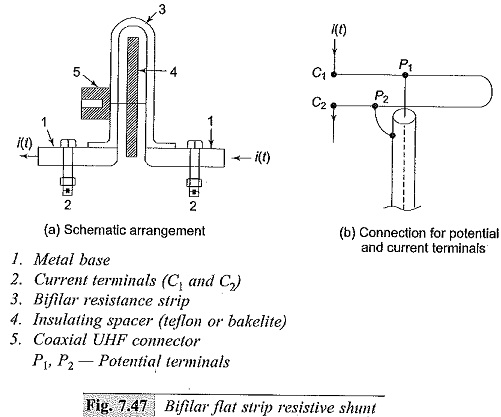
(a) Bifilar Strip Shunt
The bifilar design (Fig. 7.47) consists of resistor elements wound in opposite directions and folded back, with both ends insulated by a teflon or other high quality insulation. The voltage signal is picked up through a ultra high frequency (UHF) coaxial connector. The Low Ohmic Shunt suffers from stray inductance associated with the resistance element, and its potential leads are linked to a small part of the magnetic flux generated by the current that is measured. To overcome these problems, coaxial shunts are chosen.
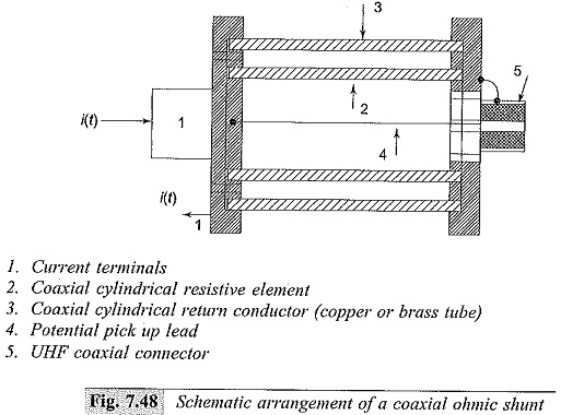
(b) Coaxial Tubular or Park’s Shunt
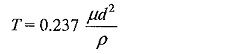
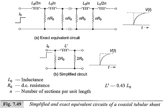
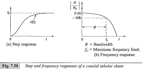
In the coaxial design (Fig. 7.48) the current is made to enter through an inner cylinder or resistive element and is made to return through an outer conducting measured between the potential pick-up point and the outer case. The space between the inner and the outer cylinder is air and hence acts like a pure insulator. With this construction, the maximum frequency limit is about 1000 MHz and the response time is a few nanoseconds. The upper frequency limits is governed by the skin effect in the resistive element. The equivalent circuit of the Low Ohmic Shunt is given in Fig. 7.49. The step response and the frequency response are shown in Fig. 7.50. The inductance L0 shown in Fig. 7.49 may be written as:
where
μ = μ0 μr; the magnetic permeability, μ0 = 4π x 10-7
d = thickness of the cylindrical tube,
l = length of the cylindrical tube, and
r = radius of the cylindrical tube
The effective resistance is given by
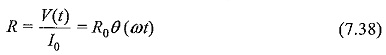
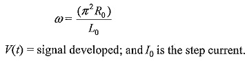
where Re = the d.c. resistance; Lo = inductance for d.c. currents and 0(00 is the theta function of type 3 and is equal to
![]()
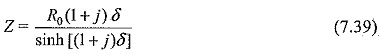
The effective impedance of the shunt for any frequency f according to Silsbee is given by:
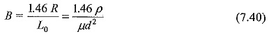
The simplified equivalent circuit shown in Fig. 7.49 is convenient to calculate the rise time of the Low Ohmic Shunt. The rise time accordingly is given by,
and the bandwidth is given by
The coaxial tubular shunts were constructed for current peaks up to 500 kA; Low Ohmic Shunt constructed for current peaks as high as 200 kA with di/dt of about 5 x 10¹⁰ A/s have induced voltages less than 50 V and the voltage drop across the shunt was about 100 V.
(c) Squirrel Cage Shunts
In certain applications. such as post arc current measurements. high ohmic value
Low Ohmic Shunt are not suitable due to their limitations of heat dissipation, larger wall thickness, and the skin effect. To overcome these problems, the resistive cylinder is replaced by thick rods or strips, and the structure resembles the rotor construction of double squirrel cage induction motor.
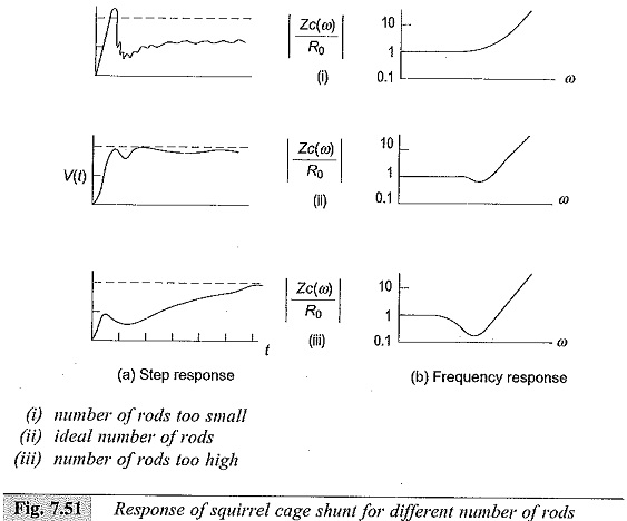
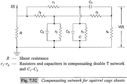
The equivalent circuit for squirrel cage construction is different, and complex. The shunts show peaky response for step input, and a compensating network has to be designed to get optimum response. In Fig. 7.51, the step response (Fig. 7.51a) and frequency response (Fig..7.51b) characteristics are given. Rise times of better than 8 ns with bandwidth more than 400 MHz were obtained for this type of shunts. A typical R-C compensating network used for these shunts is shown in Fig. 7.52.
(d) Material and Technical Data for the Current Shunts
The important factor for the materials of the shunts is the variation of the resistivity of the material with temperature. In Table 7.11 physical properties of some materials with low temperature coefficient, which can be used for shunt construction are given.
The importance of the skin effect has been pointed out in the coaxial shunt design. The skin depth d for a material of conductivity σ at any frequency f is given by
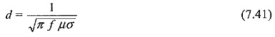
Skin depth, d, is defined as the distance or depth from the surface at which the magnetic field intensity is reduced to ‘1/e’ (e = 2.718 …) of the surface value for a given frequency f. Materials of low conductivity σ (high resistivity materials) have large skin depth and hence exhibit less skin effect.
It may be stated that low ohmic shunts of coaxial type or squirrel cage type construction permit measurements of high currents with response times less than 10 ns.