Long Transmission Line Voltage:
It is well known that line constants of the transmission line are uniformly distributed over the entire length of the line. However, reasonable accuracy can be obtained in line calculations for short and medium lines by considering these constants as lumped. If such an assumption of lumped constants is applied to Long Transmission Line Voltage (having length excess of about 150 km), it is found that serious errors are introduced in the performance calculations. Therefore, in order to obtain fair degree of accuracy in the performance calculations of Long Transmission Line Voltage, the line constants are considered as uniformly distributed throughout the length of the line. Rigorous mathematical treatment is required for the solution of such lines.
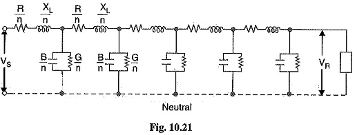
Fig. 10.21 shows the equivalent circuit of a 3-phase Long Transmission Line Voltage on a phase-neutral basis. The whole line length is divided into n sections, each section having line constants 1/n th of those for the whole line. The following points may by noted :
The line constants are uniformly distributed over the entire length of line as is actually the case.
- The resistance and inductive reactance are the series elements.
- The leakage susceptance (B) and leakage conductance (G) are shunt elements. The leakage susceptance is due to the fact that capacitance exists between line and neutral. The leakage conductance takes into account the energy losses occurring through leakage over the insulators or due to corona effect between conductors. Admittance = √G2 + B2.
- The leakage current through shunt admittance is maximum at the sending end of the line and decreases continuously as the receiving end of the circuit is approached at which point its value is zero.
Analysis of Long Transmission Line Voltage (Rigorous method)
Fig. 10.22 shows one phase and neutral connection of a 3-phase hue with impedance and shunt admittance of the line uniformly distributed.
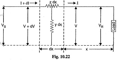
Consider a small element in the line of length dx situated at a distance x from the receiving end.
Let
z = series impedance of the line per unit length
y= shunt admittance of the line per unit length
V = voltage at the end of element towards receiving end
V+ dV = voltage at the end of element towards sending end
I + dI = current entering the element dx
I = current leaving the element dx
Then for the small element dx,
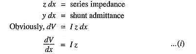
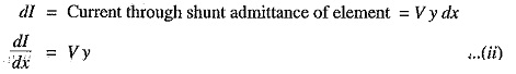
Now, the current entering the element is I + dl whereas the current leaving the element is I. The difference in the currents flows through shunt admittance of the element i.e.,
Differentiating eq. (i) w.r.t x, we get,
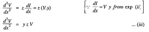
The solution of this differential equation is
![]()
Differentiating exp. (iv) w.r.t. x, we have,
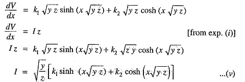
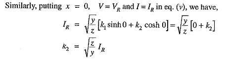
Equations (iv) and (v) give the expressions for V and I in the form of unknown constants k1 and k2. The values of k1 and k2 can be found by applying end conditions as under :
![]()
Putting these values in eq. (iv), we have,
![]()
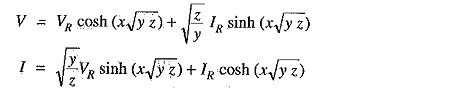
Substituting the values of k1 and k2 in eqs. (iv) and (v), we get,
The sending end voltage (VS) and sending end current (IS) are obtained by putting x = 1 in the above equations i.e.,
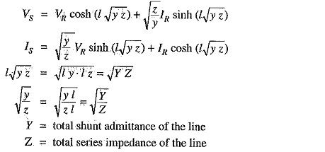
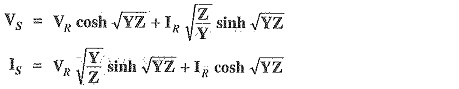
Therefore, expressions for VS and IS become
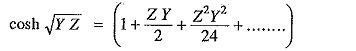
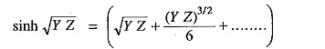
It is helpful to expand hyperbolic ine and cosine in terms of their power series.