Load Capacitance Effect:
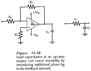
Capacitance connected at the output of an operational amplifier is termed Load Capacitance Effect (CL). Figure 15-20 shows that CL is in series with the op-amp output resistance (ro), so CL and ro constitute a phase-lag circuit in the feedback network. As in the case of stray capacitance, another 10° of phase lag introduced by CL and ro could cause circuit instability where the phase margin is already small. The equation for calculating the Load Capacitance Effect that might cause instability is similar to that for stray capacitance;
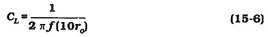
In Eq. 15-6 f is the frequency at which AvB = ACL. If ro is reduced, Eq 15-6 gives a larger CL value. Thus, an op-amp with a low output resistance can tolerate more Load Capacitance Effect than one with a higher output resistance.
One method often used to counter instability caused by load capacitance is shown in Fig. 15-21(a). A resistor (Rx) usually ranging from 12 Ω to 400 Ω, is connected in series with the Load Capacitance Effect. The presence of Rx (with R2 connected at the op-amp output) can severely reduce the phase lag produced by ro and CL. However, Rx also has the undesirable effect of increasing the circuit output impedance to approximately the resistance of Rx.
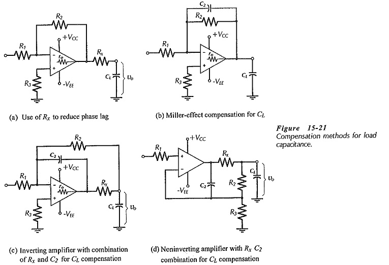
A Miller-effect capacitor (C2) connected across feedback resistor R2 may be used to compensate for the load capacitance, [see Fig. 15-21(b)]. In this case, C2 introduces some phase-lead in the feedback network to counter the phase-lag. The equation for calculating a suitable capacitance for C2 is, once again, similar to that for stray capacitance;
![]()
A modified form of Miller-effect compensation for load capacitance is shown in Fig. 15-21(c). An additional resistor (Rx) is included in series with CL to reduce the phase lag, as discussed. But now, R2 is connected at the junction of Rx and CL, so that (because of feedback) Rx has no significant effect on the circuit output impedance. Also, C2 is connected from the op-amp output terminal to the inverting input. With this arrangement, Eq. 15-7 is modified to,
![]()
It should be noted from Equations 15-7 and 15-8 that, as for stray capacitance, smaller resistance values for R2 give larger, more convenient, compensating capacitor values.