Lens Antenna Design:
The paraboloid reflector is one example of how optical principles may be applied to microwave lens antenna, and the Lens Antenna is yet another. It is used as a collimator at frequencies well in excess of 3 GHz and works in the same way as a glass lens used in optics.
Principles of Lens Antenna:
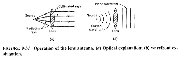
Figure 9-37 illustrates the operation of a dielectric lens antenna. Looking at it from the optical point of view, as in Figure 9-37a, we see that refraction takes place, and the rays at the edges are refracted more than those near the center. A divergent beam is collimated, as evidenced by the fact that the rays leaving the lens are parallel. It is assumed that the source is at the focal point of the lens. The reciprocity of antennas is nicely illustrated.
If a parallel beam is received, it will be converged for reception at the focal point. Using an electromagnetic wave approach, we note that a curved wavefront is present on the source side of the lens. We know that a plane wavefront is required on the opposite side of the lens; to ensure a correct phase relationship. The function of the Lens Antenna must therefore be to straighten out the wavefront. The lens does this, as shown in Figure 9-37b, by greatly slowing down the portion of the wave in the center.
The parts of the wavefront near the edges of the lens are slowed only slightly, since those parts encounter only a small thickness of the dielectric material in which velocity is reduced. Note that, in order to have a noticeable effect on the velocity of the wave, the thickness of the lens at the center must be an appreciable, number of wavelengths.
Practical considerations:
Lens Antenna are often made of polystyrene, but other materials are also employed. All suffer from the same problem of excessive thickness at frequencies below about 10 GHz. Magnifying glasses (the optical counterparts) are in everyday use, but what is not often realized is how thick they are when compared to the wavelength of the “signal” they pass. The thickness in the center of a typical magnifying glass may well be 6 mm, which, compared to the 0.6-μm wavelength of yellow light, is exactly 10,000 wavelengths! Dielectric antenna lenses do not have to be nearly as thick, relatively, but it is seen that problems with thickness and weight can still arise.
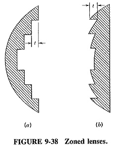
Figure 9-38 shows the zoning, or stepping, of dielectric lenses. This is often used to cure the problem of great thickness required of lenses used at lower microwave frequencies or for strongly curved wavefronts. Not only would the lens be thick and heavy without zoning, but it would also absorb a large proportion of the radiation passing through it. This is because any dielectric with a large enough refractive index must, for that very reason, absorb a lot of power.
The function of a Lens Antenna is to ensure that signals are in phase after they have passed through it. A stepped lens will ensure this, despite appearances. What happens simply is that the phase difference between the rays passing through the center of the lens, and those passing through the adjacent sections, is 360° or a multiple of 360° this still ensures correct phasing. To rephrase it, we see that the curved wavefront is so affected that the center portion of it is slowed down, not enough for the edges of the wavefront to catch up, but enough for the edges of he previous wavefront to catch the center portion. A disadvantage of the zoned lens is a narrow bandwidth. This is because the thickness of each step, t, is obviously related to the wavelength of the signal.
However, since it effects a great saving in bulk, it is often used. Of the two zoning methods, the method of Figure 9-38b is preferable, since it yields a lens that is stronger mechanically than that of Figure 9-38a.
Applications of Lens Antenna:
The Lens Antenna his two major applications. It may be employed to correct the curved wavefront from a shallow horn (in which case it is mounted directly over the mouth of the horn) or as an antenna in its own right. In the latter instance, lenses may be used in preference to parabolic reflectors at millimeter and sub-millimeter frequencies. They have the advantages of greater design tolerances and the fact that there is no primary antenna mount to obstruct radiation. The disadvantages are greater bulk, expense and design difficulties.