Introduction to Television:
Introduction to Television tells first thing of seeing at a distance. To be successful, a television system may be required to reproduce faithfully:
-
The shape of each object, or structural content
-
The relative brightness of each object, or tonal content
-
Motion, or kinematic content
-
Sound
-
Color, or chromatic content
-
Perspective, or stereoscopic content
If only the structural content of each object in a scene were shown, we would have truly black-and-white TV (without any shades of gray). If tonal content were added, we would have black-and-white still pictures. With items 3 and 4 we would have, respectively, “movies” and “talkies.” The last two items are not essential, although most people consider color TV desirable, and the next generation will probably include item 6.
The human eye contains many millions of photosensitive elements, in the shape of rods and cones, which are connected to the brain by some 800,000 nerve fibers (i.e., channels). A similar process by the camera tube is used at the transmitting station and the picture tube in the TV receiver. Some 150,000 effective elements are displayed in each scene. The use of that number of channels is out of the question. A single channel is used instead, each element being scanned in succession, to convey the total information in the scene. This is done at such a high rate that the eye sees the whole scene, without being aware of the scanning motion. A single static picture results.
The problem of showing motion was solved long ago in the motion picture industry. A succession of pictures is shown, each with the scene slightly altered from the previous one. The eye is fooled into seeing continuous motion through the property known as the persistence of vision. There are 30 pictures (or “frames,” as they are called) per second in the U.S. Introduction to Television system. The number of frames is related to the 60-Hz frequency of the ac voltage system and is above the minimum required (about 18 frames per second) to make the eye believe that it sees continuous motion. Commercial films are run at 24 frames per second; while the perception of smooth motion still results, the flicker due to the light cutoff between frames would be obvious and distracting. In motion pictures, this is circumvented by passing the shutter across the lens a second time, while the frame is still being screened, so that a light cutoff occurs 48 times per second. This is too fast for the eye to notice the flicker. The same effect could be obtained by running film at 48 frames per second, but this would result in all films being twice as long as they need be (to indicate smooth motion). ,
To explain how flicker is avoided in TV, it is first necessary to look at the scanning process in a little detail. The moving electron beam is subjected to two motions simultaneously. One is fast and horizontal, and the other is vertical and slow, being 262 1/2 times slower than the horizontal motion. The beam gradually moves across the screen, from left to right, while it simultaneously descends almost imperceptibly. A complete frame is covered by 525 horizontal lines, which are traced out 30 times per second. However, if each scene were shown traced thus from top to bottom (and left to right), any given area of the picture tube would be scanned once every one-thirtieth of a second, too slowly to avoid flicker. Doubling the vertical speed, to show 60 frames per second, would do the trick but would double the bandwidth.
The solution, as will be explained in the Introduction to Television, consists in subdividing each frame into two fields. One field covers even-numbered lines, from top to bottom, and the second field fills in the odd-numbered lines. This is known as interlaced scanning, and all the world’s TV systems use it. We still have 30 frames per second, but any given area of the display tube is now illuminated 60 times per second, and so flicker is too fast to be registered by the eye.
The scene elements at the transmitting station are produced by a mosaic of photosensitive particles within the camera tube, onto which the scene is focused by optical means. They are scanned by an electronic beam, whose intensity is modulated by the brightness of the scene. A varying voltage output is thus obtained, proportional to the instantaneous brightness of each element in turn. The varying voltage is amplified, impressed as modulation upon a VHF or UHF carrier, and radiated. At the receiver, after amplification and demodulation, the received voltage is used to modulate the intensity of the beam of a CRT. If this beam is made to cover each element of the display screen area exactly in step with the scan of the transmitter, the original scene will then be synthesised at the receiver.
The need for the receiver picture tube to be exactly in step with that of the transmitter requires that appropriate information be sent. This is Synchronising; or sync information, which is transmitted in addition to the picture information. The two sets of signals are interleaved in a kind of time-division multiplex, and the picture carrier is amplitude-modulated by this total information. At the receiver, signals derived from the transmitted sync control the vertical and horizontal scanning circuits, thus ensuring that the receiver picture tube is in step with the transmitter camera tube.
Black-and-white television can be transmitted in this manner, but color TV requires more information. As well as indicating brightness or luminance, as is done in black-and-white TV, color (or actually hue) must also be shown. That is, for each picture element we must show not only how bright it is, but also what hue this element should have, be it white, yellow, red, black or any other. The hue is indicated by a chrominance, or chroma, signal.
The colors actually indicated are red, green and blue, but all other colors can be synthesised from these three. Separate signals for each of the three colors are produced by the transmitter camera tube. In the receiver, these signals are applied to the three guns of the picture tube, or kinescope. The screen consists of adjacent green, blue and red dots, which luminesce in that color when the scanning beam falls on them. Needless to say, the beams themselves are not colored! They merely indicate to each colored dot on the screen how bright it should be at any instant of time, and the combination of brightnesses of these three colors reproduces the actual hues we see. Because of the smallness of the color dots and our distance from the screen, we see color combinations instead of the individual dots.
Color TV will be discussed in more detail later in this chapter, but it is worth mentioning at this stage that FDM is used to interleave the chrominance signal with luminance. The process is quite complex. The chroma signal is assigned portions of the total frequency spectrum which luminance does not use. The situation is complicated by the fact that color and black-and-white TV must be compatible. That is to say, the chroma signals must be coded in such a way that a satisfactory picture will be produced (in black and white) by a monochrome receiver tuned to that channel. Conversely, color TV receivers must be designed so that they are able to reproduce satisfactorily (in black and white) a transmitted monochrome signal.
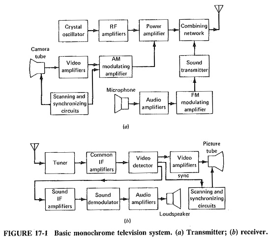
The simplest item has been left until last; this is the sound transmission. A separate transmitter is used for sound, connected to the Same antenna as the picture transmitter. However, it is a simple matter to have a receiver with common amplification for all signals up to a point, at which the various signals go to their respective sections for special processing. This separating point is almost invariably the video detector, whose output consists of picture, sync and sound information. The sound signal is amplified, applied to its own detector, amplified again and fed to a loudspeaker. The modulating system used for sound in the U.S. system, and most other major systems around the world, is wideband FM. It is not quite as wideband as in FM radio transmissions, but it is quite adequate for good sound reproduction. The transmitting frequency for the sound transmitter is quite close to the picture transmitting frequency. The one tuning mechanism and amplifiers can handle both. A block diagram of a Basic Monochrome Television System is now shown in Figure 17-1, indicating basically how the requirements of monochrome TV transmission and reception may be met.