Interfacing 8259 with 8085:
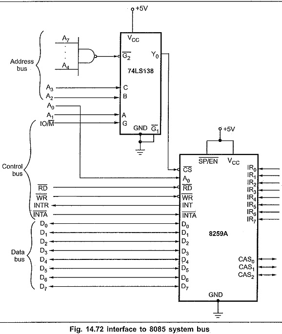
Fig. 14.72 shows Interfacing 8259 with 8085 microprocessor system.
Addressing of 8259A :
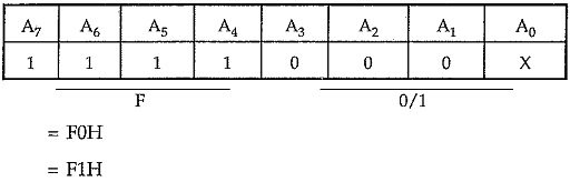
The 74LS138 address decoder will assert the CS input of the 8259A when an I/O base address is F0H or F1H on the address bus. The A0 input of the 8259A is used to select one of the two internal addresses in the device: A0 of the 8259A is connected to system line A0. So the system addresses for the two internal addresses are F0H and F1H. The data lines of an 8259A are connected to the AD0-AD7 of the system data bus, RD and WR signals are connected to the system RD and WR lines. The interrupt request signal INT from the 8259A is connected to the INTR input of the 8085 and INTA from the 8085 is connected to INTA of the 8259A. As we are using single Interfacing 8259 with 8085 in the system, SP/EN pin is tied high and CAS0-CAS2 lines are left open. The eight IR inputs are available for interrupt signals.
Note : Unused IR inputs should be tied to ground so that a noise pulse cannot accidentally cause an interrupt.
8259A Interfacing with 8086:
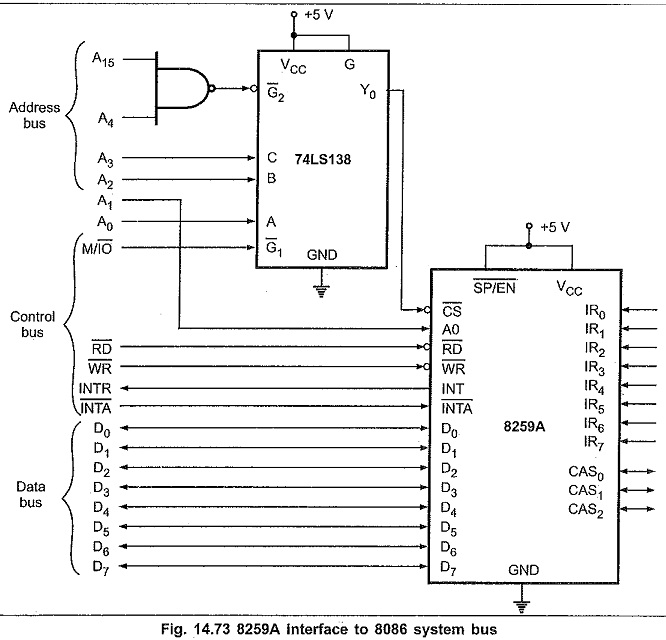
Fig. 14.73 shows that how an 8259A can be interfaced with the 8086 microprocessor system in minimum mode. In case of 8088 microprocessor same interfacing diagram can be used except M/IO signal. In 8088, M/IO signal is represented by IO/M signal, therefore this signal is connected to G (active high) signal of decoder to interface 8259A in I/O mapped I/O mode.
Addressing of 8259A :
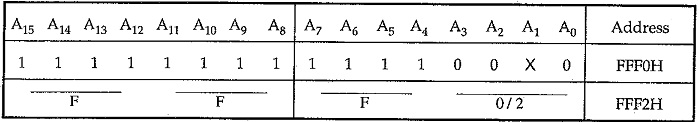
The 74LS138 address decoder will assert, the CS input of the 8259A when an I/O base address is FFF0H or FFF2H on the address bus. The A0 input of the 8259A is used to select one of the two internal addresses in the device. A0 of the 8259A is connected to system line A1. So the system addresses for the two internal addresses are FFF0H and FFF2H. The data lines of an 8259A are connected to the lower half of the system data bus, because the 8086 expects to receive interrupt types on these lower eight data lines. RD and WR signals are connected to the system RD and WR lines. The interrupt request signal INT from the 8259A is connected to the INTR input of the 8086 and INTA from the 8086 is connected to INTA on the 8259A. As we are using single 8259A in the system SP/EN pin is tied high and CAS0-CAS2 lines are left open. The eight IR inputs are available for interrupt signals.
Cascading:
The 8259A can be easily interconnected to get multiple interrupts. Fig. 14.74 (See Fig. on next page) shows how 8259A can be connected in the cascade mode. In cascade mode one 8259A is configured in Master mode and other should be configured in the Slave mode. In this figure 8259A-1 is in the master mode and others are in slave mode. Each slave 8259A is identified by the number which is assigned as a part of its initialization. Since the 8085 has only one INTR input, only one of the 8259A INT pins is connected to the 8085 INTR pin. The Interfacing 8259 with 8085 connected directly to the 8085 INTR pin is referred to as the master. The INT pins from other 8259As are connected to the IR inputs of the master 8259A. These cascaded 8259As are referred to as slave. The INTA signal is connected to both master and slave 8259A.
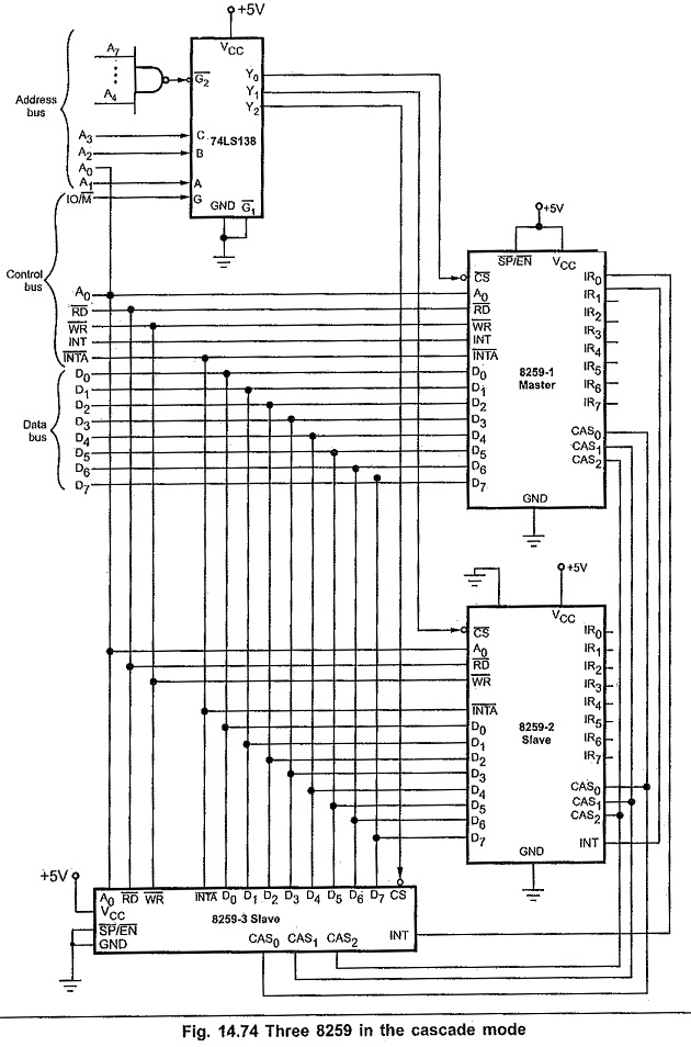
The cascade pins CAS0 to CAS2 are connected from the master to the corresponding pins of the slave. For the master these pins function as outputs, and for the slave these pins function as inputs. The SP/EN Signal is tied high for the master. However, it is grounded for the slave.
Each 8259A has its own addresses so that command words can be written to it and status bytes read from it.
Addresses for 8259As :
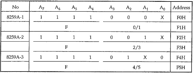
Master and slave operation :
When the slave receives an interrupt signal on one of its IR inputs, it checks mask condition and priority of the interrupt request. If the interrupt is unmasked and its priority is higher than any other interrupt level being serviced in the slave, then the slave will send an INT signal to the IR input of a master. If that IR input of the master is unmasked and if that input has higher priority than any other IR inputs currently being serviced, then the master will send an INT signal to the 8085 INTR input. If the INTR interrupt is enabled, the 8085 will go through its INTR interrupt procedure and sends three INTA pulses to both the master and the slave. In response to first interrupt acknowledge signal opcode for CALL instruction is put on the data bus and the master outputs a 3-bit slave identification number on the CAS0-CAS2 lines. Sending the 3-bit ID number enables the slave. When the slave receives the second INTA pulse from the 8085, the slave will send the low-order address byte of the ISR on the data bus. Finally, slave sends the high-order byte of . the ISR on the data bus on receiving third INTA signal.
If an interrupt signal is applied directly to one of the IR inputs of the master, the master will send the opcode for CALL instruction to the 8085 when it receives the first INTA pulse from the 8085. It then sends low-order byte and high-order byte in successive interrupt acknowledge cycles (second and third).