8255 Interfacing with 8086:
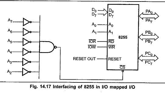
Fig. 14.17 shows the 8255 Interfacing with 8086 Microprocessor and Interfacing 8255 with 8085 Microprocessor in I/O mapped I/O technique. Here RD and WR signals are activated when IO/M signal is high, indicating I/O bus cycle. Reset out signal from 8085 is connected to the RESET signal of the 8255.
Interfacing 8255 In Memory Mapped I/O:
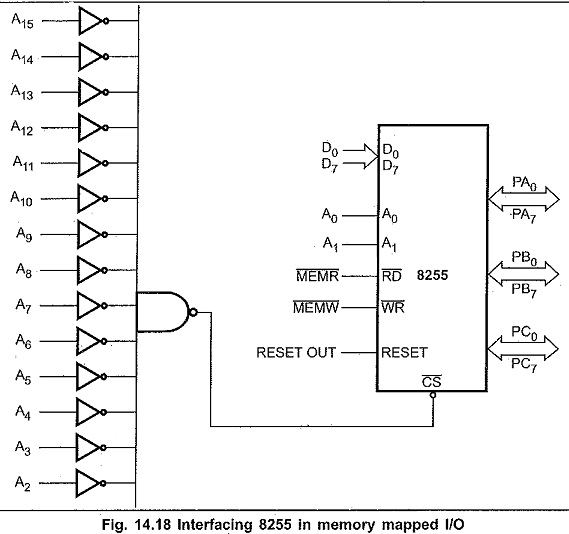
Fig. 14.18 shows the interfacing of 8255 with 8085 in memory mapped I/C technique. Here RD and WR signals are activated when 10/M signal is low, indicating memory bus cycle. To get absolute address, all remaining address lines (A15 – A2) are used to decode the address for 8255. Other signal connections are same as in I/C mapped I/O.
8255 Interfacing with 8086 in I/O Mapped I/O Mode:
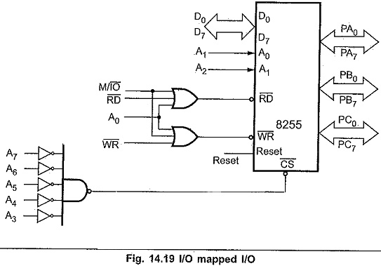
The 8086 has four special instructions IN, INS, OUT, and OUTS to transfer data through the input/output ports in I/O mapped I/O system. M/IO signal is always low when 8086 is executing these instructions. So M/IO signal is used to generate separate addresses for, memory and input/output. Only 256 (28) I/O addresses can be generated when direct addressing method is used. By using indirect address method this range can be extended upto 65536 (216) addresses.
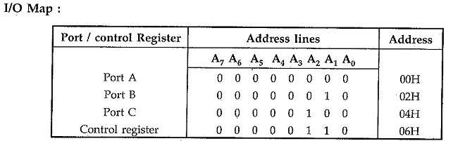
Fig. 14.19 shows the 8255 Interfacing with 8086 in I/O mapped I/O technique. Here, RD and WR signals are activated when M/IO signal is low, indicating I/O bus cycle. Only lower data bus (D0 — D7) is used as 8255 is 8-bit device. Reset out signal from clock generator is connected to the Reset signal of the 8255. In case of interrupt driven I/O INTR signal (PC3 or PC0) from 8255 is connected to INTR input of 8088.
8255 Interfacing with 8086 in Memory Mapped I/O:
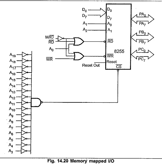
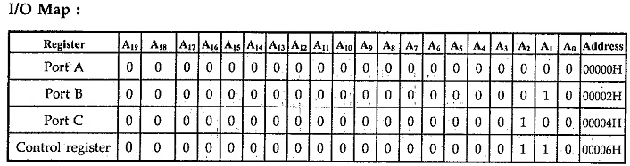
In this type of I/O interfacing, the 8086 uses 20 address lines to identify an I/O device; an I/O device is connected as if it is a memory register. The 8086 uses same control signals and instructions to access I/O as those of memory. Fig. 14.20 shows the 8255 Interfacing with 8086 in memory mapped I/O technique. Here RD and WR signals are activated when M/IO signal is high, indicating memory bus cycle. Address lines A0 – A1 are used by 8255 for internal decoding. To get absolute address, all remaining address lines (A3 – A19) are used to decode the address for 8255. Other signal connections are same as in I/O napped I/O.
Applications:
In this section we discuss many useful applications like keyboard and display interface, traffic light control, printer interface and so on.