Horn Antenna Design:
Horn Antenna Design – As we know, a waveguide is capable of radiating energy into open space if it is suitably excited at one end and open at the other. This radiation is much greater than that obtained from the two-wire transmission line described at the beginning of this chapter, but it suffers from similar difficulties. Only a small proportion of the forward energy in the waveguide is radiated, and much of it is reflected back by the open circuit. As with the transmission line, the open circuit is a discontinuity which matches the waveguide very poorly to space. Diffraction around the edges will give the radiation a poor, nondirective pattern. To overcome these difficulties, the mouth of the waveguide may be opened out, as was done to the transmission line, but this time an electromagnetic horn results instead of the dipole.
Basic horns:
When a waveguide is terminated by a horn, such as any of those shown in Figure 9-34, the abrupt discontinuity that existed is replaced by a gradual transformation. Provided that impedance matching is correct, all the energy traveling forward in the waveguide will now be radiated. Directivity will also be improved, and diffraction reduced.
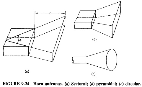
There are several possible Horn Antenna Design configurations; three of the most common are shown here. The sectoral horn flares out in one direction only and is the equivalent of the pillbox parabolic reflector. The pyramidal horn flares out in both directions and has the shape of a truncated pyramid. The conical horn is similar to it and is thus a logical termination for a circular waveguide. If the flare angle Φ of Figure 9-34a is too small, resulting in a shallow horn, the wavefront leaving the horn will be spherical rather than plane, and the radiated beam will not be directive. The same applies to the two flare angles of the pyramidal horn. If the Φ is too small, so will be the mouth area of the horn, and directivity will once again suffer (not to mention that diffraction is now more likely). It is therefore apparent that the flare angle has an optimum value and is closely related to the length L of Figure 9-34a, as measured in wavelengths.
In practice, Φ varies from 40° when L/λ = 6, at which the beamwidth in the plane of the horn in 66° and the maximum directive gain is 40, to 15° when L/λ = 50, for which beamwidth is 23° and gain is 120. The use of a pyramidal or conical horn will improve overall directivity because flare is now in more than one direction. In connection with parabolic reflectors, this is not always necessary. The Horn Antenna Design is not nearly as directive as an antenna with a parabolic reflector, but it does have quite good directivity, an adequate bandwidth (in the vicinity of 10 percent) and simple mechanical construction. It is a very convenient antenna to use with a waveguide. Simple horns such as the ones shown (or with exponential instead of straight sides) are often employed, sometimes by themselves and sometimes as primary radiators for paraboloid reflectors.
Some conditions dictate the use of a short, shallow horn, in which case the wavefront leaving it is curved, not plane as so far considered. When this is unavoidable, a dielectric lens may be employed to correct the curvature.
Special horns:
There are two Horn Antenna Design in use which are rather difficult to classify, since each is a cross between a horn and a parabolic reflector. They are the Cass-horn and the triply folded horn reflector, the latter more commonly called the hoghorn antenna.
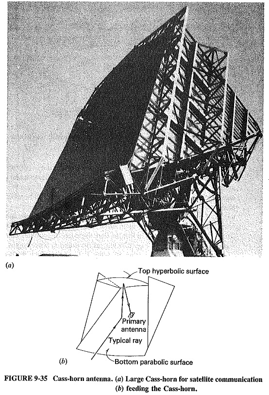
In the Cass Horn Antenna, radio waves are collected by the large bottom surface shown in Figure 9-35, which is slightly (parabolically) curved, and are reflected upward at an angle of 45°. Upon hitting the top surface, which is a large hyperbolic cylinder, they are reflected downward to the focal point which, as indicated in Figure 9-35b, is situated in the center of the bottom surface. Once there, they are collected by the conical horn placed at the focus. In the case of transmission the exact reverse happens.
This type of Horn Antenna Design reflector antenna has a gain and beamwidth comparable to those of a paraboloid reflector of the same diameter. Like the Cassegrain feed, after which it is named, it has the geometry to allow the placement of the receiver (or transmitter) at the focus, this time without any obstruction. It is therefore a low-noise antenna and is used in satellite tracking and communications stations. The one shown comes from such a station in Carnarvon.
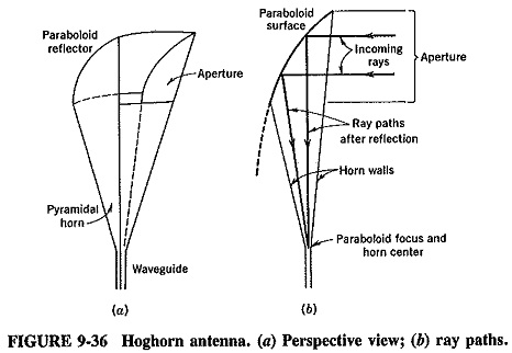
The hoghom antenna of Figure 9-36 is another combination of paraboloid and horn. It is a low-noise microwave antenna like the Cass-horn and has similar applications. It consists of a parabolic cylinder joined to a pyramidal horn, with rays emanating from, or being received at, the apex of the Horn Antenna Design. An advantage of the hoghorn antenna is that the receiving point does not move when the antenna is rotated about its axis.