High Voltage Testing of Surge Arrester:
In modern practices, surge arrester or lightning arresters are the most reliable apparatus to protect the power system against transient voltages due to lightning and switching surges. They are invariably used from distribution voltages (400 V) to highest system transmission voltages of 765 kV or above. Hence, testing them precisely in standard laboratories with standard test procedures are of great importance in modern power system practice. A High Voltage Testing of Surge Arrester has to be a non-conductor for operating power frequency voltages. It should behave as a short circuit for transient overvoltages of impulse character, discharge the heavy current, and recover its insulation without allowing the follow-up of the power frequency current.
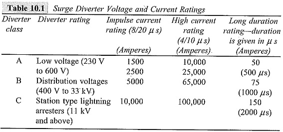
In Table 10.1, the impulse current ratings of the High Voltage Testing of Surge Arrester in relation to their voltage are given, and the testing is usually done at these current ratings.
Tests on Surge Arresters:
Power Frequency Sparkover Test:
This is routine test. This test is conducted using a series resistance to limit the current in case a sparkover occurs. The arrester has to withstand at least 1.5 times the rated value of the voltage for five successive applications. The test is generally done under dry and wet conditions also.
Hundred per cent Standard Impulse Sparkover Test:
This test is conducted to ensure that the diverter operates positively when overvoltages of impulse nature occur. The impulse generator is adjusted to give the standard impulse voltage of a preset magnitude specified in the specifications. The arrester has to sparkover every time in each of the ten successive applications. The test is done with both positive and negative polarity waveforms. Sometimes, the test is done by starting at a voltage level that does not give flashover at all, and is repeated in increasing steps of voltage till hundred per cent flashover occurs. The magnitude of the voltage at which hundred per cent flashover occurs is the required sparkover voltage.
Front of Wave Sparkover Test:
In order to ensure that the High Voltage Testing of Surge Arrester flashes over for very steep fronted waves of high peaks, this test is conducted using an overvoltage having a rate of rise of 100 kV/μs, per 12 kV of the rating. The estimated maximum steepness of the waves are specified in standards and specifications. The test is done by conducting hundred per cent sparkover voltage test for increasing magnitudes of the standard impulse wave. The time to sparkover is measured. The volt-time characteristic of the arrester is plotted, and the intersection of the V-t characteristic and the line with slope of the virtual steepness of the front gives the front of a wave sparkover voltage.
Residual Voltage Test:
This test is conducted on pro-rated diverters of ratings in the range 3 to 12 kV only. The voltage developed across the Non-Linear Resistor units (NLR) during the flow of surge currents through the arrester is called the ‘residual voltage‘. (A pro-rated arrester is a complete, suitably housed section of an arrester including series gaps and non-linear series resistors in the same proportion as in the complete arrester.) Standard impulse currents of the rated magnitudes are applied, and the voltage developed across the diverter is recorded using a suitable voltage divider and a CRO. The magnitudes of the currents are approximately 0.5, 1.0, and 2.0 times the rated currents. From the oscillogram, a graph is drawn between the current magnitudes and the voltage developed across the diverter pro-rated unit. From the graph, the residual voltage corresponding to the exact rated current is obtained.
Let
V1 = rating of the complete unit,
V2 = rating of the pro-rated unit tested,
VR1 = residual voltage of the complete unit, and
VR2 = residual voltage of the pro-rated unit.
Then, it is assumed that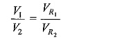
Let VRM be the maximum permissible residual voltage for the complete unit. The ratio VRM/V1 = r, is defined as a multiplying factor of the rating for the residual voltage test, which depends on V1. The “diverter” is said to pass the test, if
![]()
High Current Impulse Test on Surge Arresters:
This test is also done on pro-rated arrester units in the range of 3 to 12 kV. A high current impulse wave of 4/10 μs of peak value mentioned in the specifications is applied to a spare unit of identical characteristics. Two such applications are done on the units under test, allowing sufficient time for the cooling of the unit to the room temperature. The unit is said to pass the test, if
- the power frequency sparkover voltage before and after the test does not differ by more than 10%,
- the voltage and current waveforms of the diverter do not differ significantly in the two applications, and
- the non-linear resistance elements in the diverter do not show any sign of puncture or external flashover.
(a) Long Duration Impulse Current Test:
This test is also done on pro-rated units of 3 to 12 kV. The circuit used for generating a rectangular impulse wave consists of an artificial transmission line with lumped inductances and capacitances. The duration of the current pulse t is given by 2(n — 1) √LC, where n is the number of stages or sections used, and L and C are the inductance and capacitance of each unit. Rectangular wave is generated, if the surge impedance of the diverter is equal to √L/C at the test current. As per the specifications, 20 applications are made with specified current in five groups. The interval between the successive applications is about 1 min. It is usual to record the waveforms in the first two and the last two applications of the current wave. The diverter is said to have passed the test, if
- the power frequency sparkover voltage before and after the application of the current wave does not differ by 10%,
- The voltage across the arrester at the first and the last application does not differ by more than 8%, and
- there is no sign of puncture or other damage.
(b) Operating Duty Cycle Test:
This test is conducted on pro-rated units of arrester and gives better closeness to actual conditions. The arrester is kept energized at its rated power frequency supply voltage. The rated impulse current wave is applied first at a phase angle of about 30° from the a.c. voltage zero. If the power frequency follow-on current is not established, the angle at which current wave is applied is advanced in steps of 10° up to 90° or the peak position of the supply voltage wave till the follow-on current is established. In the course of application of the current wave, if the power frequency voltage is reduced during the flow of current, it can be compensated up to a maximum of 10% of the overvoltage. During the follow-on current period, the peak voltage across the diverter should be less than or equal to the rated peak voltage. Twenty applications of the impulse current at the selected points on the voltage wave are made in four groups. The time interval between each application is about I min, and between successive groups it is about half an hour. The arrester is said to have passed the test, if
- the average power frequency sparkover voltage before and after the test does not differ by more than 10%,
- the residual voltage at the rated current does not vary by more than 10%,
- the follow-on power frequency current is interrupted each time, and
- no significant change, signs of flashover, or puncture occurs to the prorated unit.
(c) Other Tests
The other tests that are normally conducted on High Voltage Testing of Surge Arrester are
- mechanical tests like porosity test, temperature cycle tests, and others,
- pressure relief test,
- the voltage withstand test on the insulator housing of the diverter,
- the switching surge flashover test, and
- the pollution tests.
These tests are usually done on diverters used on Extra High Voltage (EHV) systems.