Heat Sink in Transistor:
When power is dissipated in a transistor, the heat generated must flow from the collector-base junction to the case, and then to the surrounding atmosphere. When only a very small amount of power is involved, as in a small-signal transistor, the surface area of the transistor case is normally large enough to allow all of the heat to escape. For the large power dissipation that can occur in high-power transistors, the transistor surface area is not large enough. Heat Sink in Transistor must be used to increase the area in contact with the atmosphere. For small transistors, the clip-on star-type heat sinks illustrated in Fig. 8-28(a) may be used. For higher-power transistors, sheet-metal and aluminum-extrusion heat sinks are available, as illustrated in Fig. 8-28(b) and (c).
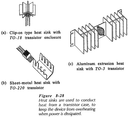
Figure 8-29(a) shows the cross section of a transistor fastened to a Heat Sink in Transistor. The heat generated at the collector-base junction must flow from the junction to the transistor case, then from the case to the heat sink, and finally from the heat sink to the surrounding air. In many cases, a mica gasket is inserted between the transistor case and the heat sink for electrical insulation, [see Fig. 8-29(a)]. Each portion of the path that the heat must pass through has a thermal resistance. These are:
θJC – junction-to-case thermal resistance
θCS – case-to-sink thermal resistance
θSA – sink-to-air thermal resistance
Figure 8-29(b) shows the thermal equivalent circuit for the transistor and heat sink. This consists of the three thermal resistances connected in series. The size of heat sink required for a transistor with a given power dissipation may be determined from the thermal equivalent circuit.
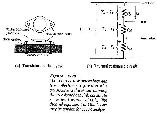
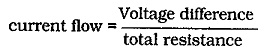
The temperature difference between the transistor collector-base Junction and the air surrounding the heat sink (TJ – TA) causes the dissipated power (Q) to flow through each of the thermal resistances in turn. The thermal resistance series circuit is analogous to an electrical series resistive circuit. The power flow in the thermal circuit is similar to the current flow in the electrical circuit. Also, the temperature drop across each thermal resistance is analogous to the voltage drop across each electrical resistance, [see Fig. 8-29(b)]. Ohm’s Law may be applied to a thermal series circuit exactly as in the case of an electrical series circuit.
For an electrical series resistive circuit, I = E/R, or,
For a series thermal resistance circuit,
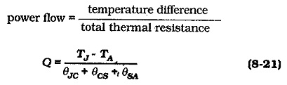
When the temperatures are. in degrees Celsius (°C), and the thermal resistances are in degrees Celsius per watt (°C /W), Q is the power dissipated in watts (W).
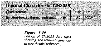
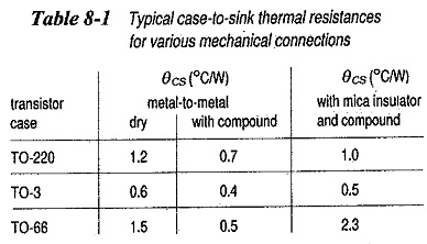
The value of θJC depends upon the transistor case style, and it is usually specified on the data sheet. See the 2N3055 data sheet portion in. Fig. 8-30. θCS is dependent on the transistor case and on the mechanical contact between the case and the Heat Sink in Transistor. The contact may be dry, have a layer of heat-conducting compound, or have an insulating gasket. Table 8-1 shows typical θCS values for three case styles and three contact conditions. θSA is determined by the size and style of the heat sink, (see Table 8-2).
Equation 8-21 may be used to calculate θSA when all other quantities are known. The smallest heat sink with a thermal resistance equal to or lower than the calculated value is then selected. Alternatively, when a given heat sink is used, Eq. 8-20 may be applied to calculate the transistor Junction temperature.
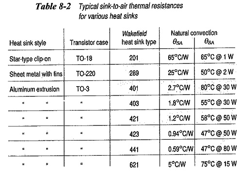
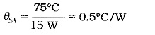
Another method used to specify heat sink thermal resistances is shown in Table 8-2. For the Wakefield 621 heat sink, θSA is listed as 75°C at 15 W for natural convection. This means that the maximum temperature difference between the case and the surrounding air will be 75°C when the Heat Sink in Transistor is dissipating 15 W. This can be redefined as,