Harmonic Equivalent Circuit of Induction Motor:
When fed from an inverter or cycloconverter, the motor terminal voltage is non-sinusoidal but it has half-wave symmetry. A non-sinusoidal waveform can be resolved into fundamental and harmonic components using Fourier analysis. Because of half-wave symmetry only odd harmonics will be present. The Harmonic Equivalent Circuit of Induction Motor can be divided into positive sequence, negative sequence and zero sequence. The harmonics, which have the same phase sequence as that of fundamental are called positive sequence harmonics. The Harmonic Equivalent Circuit of Induction Motor having phase sequence opposite to fundamental are called negative sequence harmonics. The harmonics, which have all three-phase voltages in phase are called zero sequence harmonics.
Consider the fundamental phase voltage components VAN = V1 sin ωt, VBN =V1 sin (ωt-2π/3) and VCN = V1 sin (ωt–4π/3) with the phase sequence ABC. The corresponding 5th and 7th harmonic phase voltages are
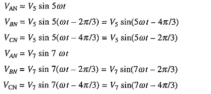
The above equations show that 7th harmonic has the phase sequence ABC, which is the same as that of fundamental. Hence it is a positive sequence harmonic. The 5th harmonic has a phase sequence ACB, hence it is a negative sequence harmonic. It can be shown that the harmonic voltages and currents of the order m = 6k + 1 (where k is an integer) are of positive sequence and harmonic voltages of the order m = 6k – 1 are of negative sequence. Similarly it can be shown that harmonics of the order m = 3k are of zero sequence. A positive sequence harmonic m will produce a rotating field, which moves in the same direction as the fundamental at a speed m times that of the fundamental field. Similarly rotating field produced by a negative sequence harmonic m will move in the direction opposite to the fundamental at m times its speed. Zero sequence components do not produce a rotating field.
For fundamental component the equivalent circuits of Fig. 6.1 will be applicable. For any mth harmonic, equivalent circuit will be as shown in Fig. 6.6(a). Each reactance has been increased by a factor m. Due to the skin effect resistances will also be increased several times. Slip sm for the mth harmonic is given by
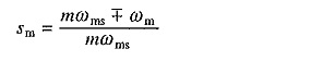
Negative sign is applicable to harmonics which produce forward rotating fields and the positive sign to those which produce backward rotating fields. Since sm is close to unity, resistance ((R′rn/sm)) has a small value. As reactances are very large compared to resistors, equivalent circuit of Fig. 6.6(a) can be replaced by the simplified circuit of Fig. 6.6(b).
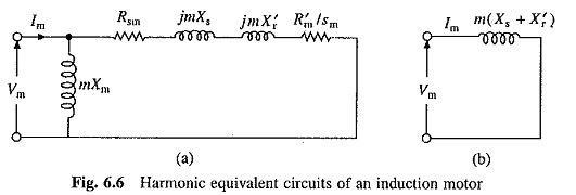
When fed from a semiconductor converter, it can be shown that the net torque produced by harmonics is close to zero. In view of this motor torque can be evaluated from equivalent circuits of Fig. 6.1(b), using Eq. (6.10), where V is the fundamental component of supply voltage. Fundamental component of rotor current is obtained from Eq. (6.4) and the /nth harmonic current is calculated from Fig. 6.6(b) as
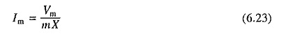
where Xs + X′r.
Generally, supply will have odd harmonics. When stator is star-connected tripplen harmonics (third harmonic and its multiples) will not flow. The rms motor current Irms will then be
![]()
When motor is delta-connected, tripplen harmonics will circulate in delta, but will not flow in the source. The source current therefore can be obtained by multiplying Irms given by Eq. (6.24) by √3. The rms motor phase current will be obtained by
![]()
For a given motor torque and power, rms current flowing through the motor has a higher value. Further due to skin effect harmonic rotor resistance has higher value. Therefore presence of harmonics increase the copper loss substantially. Core losses are also increased by harmonics. Because of increase in losses, motor has to be derated in the sense that the power output that can be obtained from machine for the same temperature rise has to be smaller. The efficiency is also reduced due to increase in losses.
Another important effect of non-sinusoidal supply is the production of pulsating torques due to interaction between the rotating field produced by one harmonic and rotor current of another harmonic. Harmonic 5, 7, 11 and 13 are major contributors of torque pulsations. 5th harmonic produces backward rotating field whereas 7th harmonic produces forward rotating field. Therefore, relative speed between the field produced by the fundamental and 5th and 7th harmonics is six time the speed of fundamental. Consequently, torque pulsations produced due to the interaction of 5th and 7th harmonic currents and the fundamental rotating field has a frequency six times the fundamental. It can be similarly shown that harmonics 11 and 13 produce torque pulsations whose frequency is 12 times the fundamental. When motor supply frequency is not very low, the frequency of torque pulsations is large enough to be filtered out by motor inertia. Consequently the torque pulsations do not have significant effect on motor speed, although they do increase noise and reduce motor life due to vibrations. However, when motor supply frequency is low, these torque pulsations cause pulsations in speed. The motor then does not move smoothly but have jerky motion.