Grounding or Earthing:
The process of connecting the metallic frame (i.e. non-current carrying part) of electrical equipment or some electrical part of the system (e.g. neutral point in a star-connected system, one conductor of the secondary of a transformer etc.) to earth (i.e. soil) is called Grounding or Earthing.
It is strange but true that grounding of electrical systems is less understood aspect of power system. Nevertheless, it is a very important subject. If grounding is done systematically in the line of the power system, we can effectively prevent accidents and damage to the equipment of the power system and at the same time continuity of supply can be maintained. Grounding or earthing may be classified as : (i) Equipment grounding (ii) System grounding.
Equipment grounding deals with earthing the non-current-carrying metal parts of the electrical equipment. On the other hand, system grounding means earthing some part of the electrical system e.g. earthing of neutral point of star-connected system in generating stations and sub-stations.
Equipment Grounding:
The process of connecting non-current-carrying metal parts (i.e. metallic enclosure) of the electrical equipment to earth (i.e. soil) in such a way that in case of insulation failure, the enclosure effectively remains at earth potential is called equipment grounding.
We are frequently in touch with electrical equipment of all kinds, ranging from domestic appliances and hand-held tools to industrial motors. We shall illustrate the need of effective equipment grounding by considering a single-phase circuit composed of a 230 V source connected to a motor M as shown in Fig. 26.1. Note that neutral is solidly grounded at the service entrance. In the interest of easy understanding, we shall divide the discussion into three heads viz. (i) Ungrounded enclosure (ii) enclosure connected to neutral wire (iii) ground wire connected to enclosure.
(i) Ungrounded enclosure: Fig. 26.1 shows the case of ungrounded metal enclosure. If a person touches the metal enclosure, nothing will happen if the equipment is functioning correctly. But if the winding insulation becomes faulty, the resistance Re between the motor and enclosure drops to a low value (a few hundred ohms or less). A person having a body resistance Rb would complete the current path as shown in Fig. 26.1.
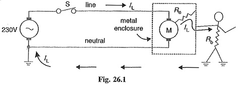
If Re is small (as is usually the case when insulation failure of winding occurs), the leakage current IL through the person’s body could be dangerously high. As a result, the person would get severe electric shock which may be fatal. Therefore, this system is unsafe.
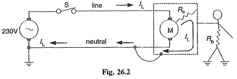
(ii) Enclosure connected to neutral wire: It may appear that the above problem can be solved by connecting the enclosure to the grounded neutral wire as shown in Fig, 26.2. Now the leakage current IL flows from the motor, through the enclosure and straight back to the neutral wire (See Fig. 26.2). Therefore, the enclosure remains at earth potential. Consequently, the operator would not experience any electric shock.
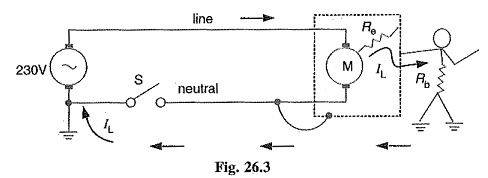
The trouble with this method is that the neutral wire may become open either accidentally or due to a faulty installation. For example, if the switch is inadvertently in series with the neutral rather than the live wire (See Fig. 26.3), the motor can still be turned on and off. However, if someone touched the enclosure while the motor is off, he would receive a severe electric shock (See Fig. 26.3). It is because when the motor is off, the potential of the enclosure rises to that of the live conductor.
(iii) Ground wire connected to enclosure: To get rid of this problem, we install a third wire, called ground wire, between the enclosure and the system ground as shown in Fig. 26,4. The ground wire may be bare or insulated. If it is insulated, it is coloured green.
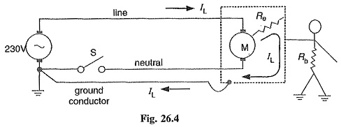
Electrical outlets have three contacts — one for live wire, one for neutral wire and one for ground wire.