First Order Low Pass Butterworth Filter:
The first order low pass butterworth filter is realized by R-C circuit used along with an op-amp, used in the noninverting configuration. The circuit diagram is shown in Fig. 2.74. This also called one pole low pass butterworth filter.
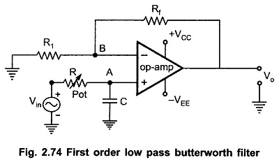
The resistances Rf and R1 decide the gain of the filter in the pass band.
Analysis for First Order Low Pass Butterworth Filter Circuit:
The impedance of the capacitor C is – j XC where XC is the capacitive reactance given by
![]()
By the potential divider rule, the voltage at the noninverting input terminal A which is the voltage across capacitor C is given by,

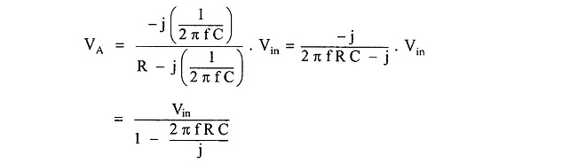


As the op-amp is in the noninverting configuration,


i.e.
where

and

and
![]()
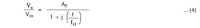
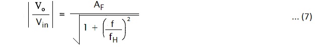
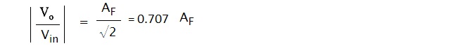
The Vo/Vin is the transfer function of the filter and can be expressed in the polar form as,

where
and

The phase angle Φ is in degrees.
The equation (7) describes the behavior of the low pass filter.
1. At very low frequencies, f < fH

2. f = fH,
3. At f > fH

Thus, for the range of frequencies, 0 < f < fH, the gain is almost constant equal to fH which is high cut off frequency. At f = fH, gain reduces to 0.707 AF i.e. 3 dB down from AF. And as the frequency increases than fH, the gain decreases at a rate of 20dB/decade. The rate 20 dB/decade means decrease of 20 dB in gain per 10 times change in frequency. The same rate can be expressed as 6 dB/octave i.e. decrease of 6 dB per two times change in the frequency. The frequency fH is called cut off frequency, break frequency, — 3dB frequency or corner frequency. The frequency response is shown in the Fig. 2.75.
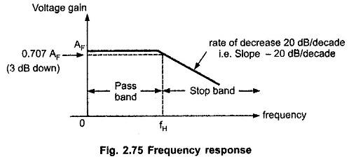
The rate of decrease in gain is 20 dB/decade i.e. the decrease can be indicated by a negative slope in the frequency response, as – 20 dB/decade.
Design Steps:
The design steps for the first order low pass Butterworth filter are
1) Choose the cut off frequency, fH.
2) Choose the capacitance C usually between 0.001 and 1 μF. Generally, it is selected as 1 μF or less than that. For better performance, mylar or tantalum capacitors are selected.
3) Now, for the RC circuit,
Hence, as fH and C are known, calculate the value of R.
4) The resistances Rf and R1 can be selected depending on the required gain in the pass band.

Frequency Scaling:
Once the filter is designed, sometimes, it is necessary to change the value of cut-off frequency fH. The method used to change the original cut-off frequency fH to a new cut-off frequency fH1 is called as frequency scaling.
To achieve such a frequency scaling, the standard value capacitor C is selected first. The required cut-off frequency can be achieved by calculating corresponding value of resistance R. But to achieve frequency scaling a potentiometer is used as shown in Fig. 2.75. Thus, the resistance R is generally a potentiometer with which required cut-off frequency fH can be adjusted and changed later on if required.