Error Detection and Correction Codes:
Error Detection and Correction Codes – Errors enter the data stream during transmission and are caused by noise and transmission system impairments. Because errors compromise the data and in some cases render it useless, procedures have been developed to detect and correct transmission errors. The processes involved with error correction normally result in an increase in the number of bits per second which are transmitted, and naturally this increases the cost of transmission. Procedures which permit error correction at the receiver location are complicated, and so it is necessary for data users to determine the importance of the transmitted data and to decide what level of Error Detection and Correction Codes is suitable for that data. The tolerance the data user has for errors will decide which error control system is appropriate for the transmission circuit being used for the user’s data.
Error Detection:
The 5-bit Baudot code provides no Error Detection and Correction Codes at all, because it uses all 5 bits to represent characters. If only 1 bit is translated (by error) to its opposite value, a totally different character will be received and the change will not be apparent to the receiver. The inability of such codes to detect errors has led to the development of other codes which provide for error control.
Constant-Ratio Codes:
A few codes have been developed which provide inherent Error Detection and Correction Codes when used in ARQ (automatic request for repeat) systems. The 2-out-of-5 code follows a pattern which results in every code group having two 1s and three 0s. When the group is received, the receiver will be able to determine that an error has occurred if the ratio of 1s to 0s has been altered. If an error is detected, a NAK (do not acknowledge) response is sent and the data word is repeated. This testing procedure continues word for word.
This code has some limitations. An odd number of errors will always be detected, but an even number of errors may go undetected. Even more limiting is the problem that this code will severely reduce the number of available code combinations. The formula
![]()
Where
! = Factorial
T = Total bits
M = Number of 1s
expresses the number of combinations possible for any code of this type. For the 2-out-of-5 code the formula is:
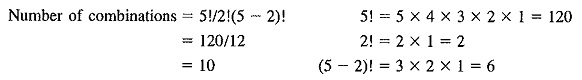
Ten combinations would prevent the code from being used for anything other than numbers.
Another code, the 4-out-of-8, is based on the same principle as the 2-out-of-5 code. The larger number of bits provides a larger number of combinations, 70, and the code also provides improved Error Detection and Correction Codesn. Owing to the redundancy of the code, its efficiency for transmission is reduced. It shows that if there were no restriction of the number of 1s in a code group, 8 bits would provide 40,320 combinations, 576 times as many as are provided by the 4-out-of-8 code. Codes such as the 2-out-of-5 and 4-out-of-8, which depend on the ratio of 1s to 0s in each code group to indicate that errors have occurred, are called Constant-Ratio Codes.
Redundant Codes:
Most Error Detection and Correction Codes systems use some form of redundancy to check whether the received data contains errors. This means that information additional to the basic data is sent. In the simplest system to visualize, the redundancy takes the form of transmitting the information twice and comparing the two sets of data to see that they are the same. Statistically, it is very unlikely that a random error will occur a second time at the same place in the data. If a discrepancy is noted between the two sets of data, an error is assumed and the data is caused to be re-transmitted. When two sets of data agree, error-free transmission is assumed.
Retransmission of the entire message is very inefficient, because the second transmission of a message is 100 percent redundant. In this case as in all cases, redundant bits of information are unnecessary to the meaning of the original message. It is possible to determine transmission efficiency by using the following formula:
![]()
In the above case of complete retransmission, the number of information bits is equal to one-half the number of total bits. The transmission efficiency is therefore equal to 0.5, or 50 percent. In a system with no redundancy, information bits equal total bits and the transmission efficiency is 100 percent. Most systems of Error Detection and Correction Codes fall between these two extremes, efficiency is sacrificed to obtain varying degrees of security against errors which would otherwise be undetected.
Parity-Check Codes:
A popular form of Error Detection and Correction Codes employing redundancy is the use of a parity-check bit added to each character code group. Codes of this type are called parity-check codes. The parity bit is added to the end of the character code block according to some logical process. The most common parity-check codes add the 1s in each character block code and append a 1 or 0 as required to obtain an odd or even total, depending on the code system. Odd parity systems will add a 1 if addition of the 1s in the block sum is odd. At the receiver, the block addition is accomplished with the parity bit intact, and appropriate addition is made. If the sum provides the wrong parity, an error during transmission will be assumed and the data will be retransmitted.
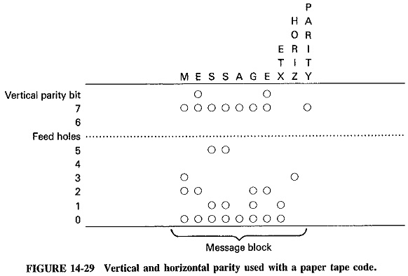
Parity bits added to each character block provide what is called vertical parity, which is illustrated in Figure 14-29. The designation vertical parity is explained by the figure which shows the parity bit at the top of each column on the punched tape.
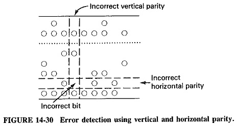
Parity bits can also be added-to rows of code bits. This is called horizontal parity and is also illustrated by Figure 14-29. The code bits are associated into blocks of specific length with the horizontal parity bits following each block. By using the two parity schemes concurrently, it becomes possible to determine which bit is in error. This is explained in Figure 14-30, where even parity is expected for both horizontal and vertical parity. Note that here one column and one row each display improper parity. By finding the intersection of the row and column, the bit in error can be identified. Simply changing the bit to the opposite value will restore proper parity both horizontally and vertically. These types of parity arrangements are sometimes called geometric codes.
Another group of parity-check codes are referred to as cyclic codes. These use shift registers with feedback to create parity bits based on polynomial representations of the data bits. The process is somewhat involved and will not be fully described here, but basically it involves processing both transmitted and received data with the same polynomial. The remainder after the receive processing will be zero if no errors have occurred. Cyclic codes provide the highest level of error detection for the same degree of redundancy of any parity-check code. The Motorola MC8503 is an LSI chip which has been developed for use in cyclic redundancy systems. The chip provides for use in systems which utilize any of four more common polynomials. The polynomial to be used is selected by a three-digit code which is applied to the chip. The MC8503 is typical of the Error Detection and Correction Codes sophistication which is possible with microchip technology.
One additional type of parity-check encoding scheme differs from those described previously in that it does not require the data to be grouped into blocks. Instead, the data is treated as a stream of information bits into which parity bits are interspersed according to standard rules of encoding. The process is more involved than some of the other schemes and is typically reserved for higher-data-speed applications. Convolutional codes, as these are called, are particularly well suited to systems which utilize forward error-correcting procedures as described below.
Error Correction:
Detecting errors is clearly of little use unless methods are available for the correction of the detected errors. Correction is thus an important aspect of data transmission.
Retransmission:
The most popular method of error correction is retransmission of the erroneous information. For the retransmission to occur in the most expeditious manner, some form of automatic system is needed. A system which has been developed and is in use is called the automatic request for repeat (ARQ), also called the positive acknowledgment/negative acknowledgment (ACK/NAK) method. The request for repeat system transmits data as blocks. The parity for each block is checked upon receipt, and if no parity discrepancy is noted, a positive acknowledgment (ACK) is sent to the transmit station and the next block is transmitted. If, however, a parity error is detected, a negative acknowledgment (NAK) is made to the transmit station which will repeat the block of data. The parity check is again made and transmission continues according to the result of the parity check. The value of this kind of system stems from its ability to detect errors after a small amount of data has been sent. If retransmission is needed, the redundant transmission time is held to a minimum. This is much more efficient than retransmission of the total message if only one or two data errors have occurred.
Forward Error-Correcting Codes:
For transmission efficiency, error correction at the receiver without retransmission of erroneous data is naturally preferred, and a number of methods of accomplishing this are available. Codes which permit correction of errors by the receive station without retransmission are called forward error-correcting codes. The basic requirement of such codes is that sufficient redundancy be included in the transmitted data for error correction to be properly accomplished by the receiver without further input from the transmitter.
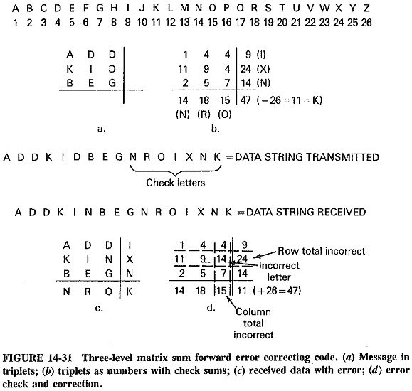
One forward error-correcting code is the matrix sum, shown in Figure 14-31, which illustrates the use of a three-level matrix sum system. Note that the sum of the rows is equal to the sum of the columns; this is important for the encoding scheme’s ability to find and correct errors. The transmitted message consists of the information bits plus the letters representing the sum of each column and row and the total. When received, the matrix is reconstructed and the sums are checked to determine whether they agree with the original sums. If they agree, error:free transmission is assumed, but if they disagree, errors must be present. The value of using this method is that it makes it possible for the receiver not only to determine which sums are incorrect but also to correct the erroneous values. In Figure 14-31a, note that the row and column discrepancies identify the matrix cell that is incorrect. By replacing the incorrect number with the value which agrees with the check sums, the message can be restored to the correct form. Such error correction requires intervention by a computer or by a smart terminal of some kind. The transmission efficiency also suffers when this kind of code is used.
If retransmission is used instead, the redundancy it requires can easily offset the inefficiency of the matrix sum code. Forward en–or correction is particularly well suited to applications which place a high value on the timeliness of data reception.
A three-level matrix sum code will provide for approximately 90 percent error-correction confidence. Larger matrices will increase this confidence level significantly, and it may be shown that a nine-level matrix will provide a 99.9 percent confidence level. The larger matrix has the additional benefit of increasing the ratio of information bits to error check bits. The result of this is increased transmission efficiency, 81 percent– for the nine-level matrix versus 56 percent for the three-level matrix.
An interesting Error Detection and Correction Codes is the hamming code, named for R. W. Hamming, an error-correction pioneer. This code adds several parity-check bits to a data word, Consider the data word 1101. The hamming code adds three parity bits to the data bits as shown below:
![]()
The first parity bit, P1, provides even parity from a check of bit locations 3, 5, and 7, which are 1, 1, and 1, respectively. P1 will therefore be 1 to achieve even parity. P2 checks locations 3, 6, and 7 and is therefore a 0 in this case. Finally, P3 checks locations 5, 6, and 7 and is a 0 here. The resulting 7-bit word is:
![]()
If the data word is altered during transmission, so that location five changes from a 1 to a 0, the parity will no longer be correct. The hamming encoding permits evaluation of the parity bits to determine where errors occur. This is accomplished by assigning a 1 to any parity bit which is incorrect and a 0 to one which is correct. If the three parity bits are all correct, 0 0 0 results and no errors can be assumed. In the case of the above described error, the code has the form:
![]()
P1 (which checks location 3, 5, and 7) should now be a 1 and is therefore incorrect. It will be given a 1. P2 checks 3, 6, and 7 and is therefore still correct. It receives a value of 0. P3 checks 5, 6, and 7 and should be a 1, but it is wrong here, and so it receives a value of 1. The three values result in the binary word 1 0 1, which has a decimal value of 5. This means that the location containing the error is five, and the receiver has been able to pinpoint the error without retransmission of data.
The hamming code is therefore capable of locating a single error, but it fails if multiple errors occur in the one data block.
Codes such as the hagelbarger and bose-chaudhuri are capable of detecting and correcting multiple errors, by increasing the number of parity bits to accomplish their error correction. In the case of the hagelbarger code, one parity bit is sent after each data bit. This represents 100 percent redundancy. It may be shown that the code can correct up to six consecutive errors, but error bursts must be separated by large blocks of correct data bits. The bose-chaudhuri code can be implemented in several forms with different ratios of parity bits to data bits. The code was first implemented with 10 parity bits per 21 data bits. Redundancy again approaches 100 percent.
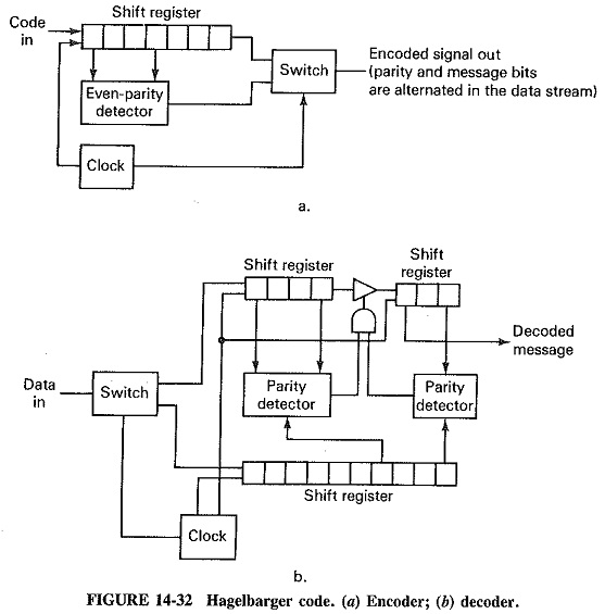
Figure 14-32 illustrates the use of shift registers and logic devices to implement the hagelbarger code. The increased complexity and decreased transmission efficiency are offset by improved immunity to transmission errors for data requiring high degrees of accuracy.