Emitter Current Feedback Circuit:
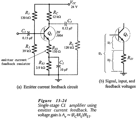
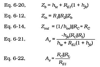
Emitter Current Feedback Circuit is produced by connecting an unbypassed resistor in series with the emitter terminal of a transistor, as shown in Fig. 13-24(a). The effects of an unbypassed emitter resistor in a CE circuit have been analyzed already, where it is shown that the circuit impedance and voltage gains are;
Equation 6-20 shows that the input impedance at the base of a transistor with an unbypassed emitter resistor is considerably increased above its normal value without feedback (hie). This raises the circuit input impedance, as defined by Eq. 6-12.
Therefore,
emitter current feedback increases the circuit input impedance.
Figure 13-24(b) shows that the circuit feedback loop is from the transistor base to the emitter, then back to the base again. The collector resistor is outside the feedback loop. The circuit output impedance remains approximately equal to RC, (see Eq. 6-14). So,
emitter current feedback has no effect on the circuit output impedance.
The precise voltage gain for the circuit in Fig. 13-24(a) is given by Eq. 6-21, and Eq. 6-22 can be used for calculation of the approximate voltage gain. Equation 6-22 is derived from Eq. 6-21 by assuming that hie ≪ RE1(1 + hfe). Using typical values of RE1 = 100 Ω, hfe = 100,
![]()
This is ten times the typical value for hie. So, Eq. 6-22 gives a reasonably close approximation to the circuit voltage gain.
It is apparent that,
emitter current feedback stabilizes single-stage amplifier voltage gain.
Circuit Design:
As in the case of other negative feedback amplifiers, an Emitter Current Feedback Circuit should first have its resistor values calculated as for a circuit without feedback. Resistor RE1 is then determined from Eq. 6-22, and RE2 is reduced to its original value minus RE1, if RE1 is large enough to affect the circuit bias conditions. The input and output coupling capacitors are calculated in the usual way, remembering that Zin is increased by the presence of RE1. The equation for the emitter bypass capacitor is rewritten to take RE1 into account. Emitter bypass capacitor Equation was derived from the fact that XC2 must equal the impedance in series with C2 at the lower cutoff frequency for the circuit. For the circuit in Fig. 13-24(a),
![]()
usually, RE1 ≫ hib, so the capacitor can be calculated from,
![]()
Two-Stage Circuit with Emitter Current Feedback Circuit:
All of the two-stage amplifiers discussed already can be designed to use Emitter Current Feedback Circuit for voltage gain stabilization and Increased input impedance. The design procedures are essentially those already discussed.
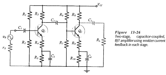
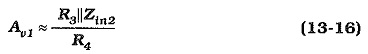
Consider the two-stage, capacitor-coupled circuit in Fig. 13-26. The voltage gain for stage-1 is,
From Eq. 6-22,
and for stage-2,
The overall voltage gain is,
![]()
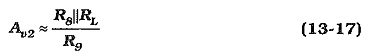
When designing a two-stage circuit with Emitter Current Feedback Circuit, the gain of each stage is determined as,
![]()
Although the two stages can be designed for identical gains, R3||Zi2 is unlikely to equal R8||RL. So, R4 and R9 are likely to be unequal.
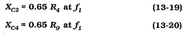
For the reasons discussed already, The emitter bypass capacitors are determined from,
The circuit input impedance is, once again, given by Eqs. 6-20 and 6-12, and the output impedance is simply the collector resistor in the second stage, (see Eq. 6-14).
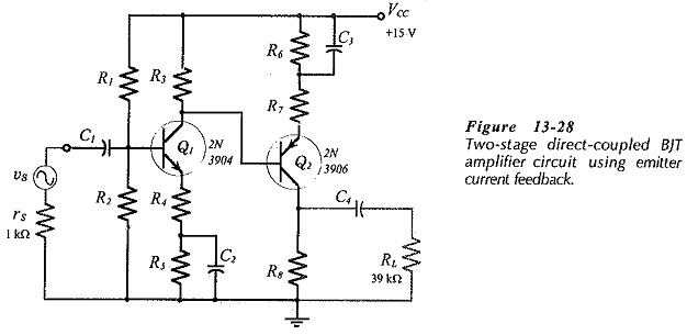
Other two-stage circuits can be designed to use emitter current bias, (for example, see Fig. 13-28). However, series voltage feedback produces more stable (closed-loop) voltage gains than single-stage Emitter Current Feedback Circuit. Series voltage feedback also produces reduced output impedance, as well as increased input impedance. Emitter current feedback increases the circuit input impedance, but leaves the output impedance unaffected. Consequently, overall series voltage negative feedback is normally preferable to single-stage Emitter Current Feedback Circuit.