Electric Supply System:
The conveyance of electric power from a power station to consumers’ premises is known as Electric Supply System.
An electric supply system consists of three principal components viz., the power station, the transmission lines and the distribution system. Electric power is produced at the power stations which are located at favorable places, generally quite away from the consumers. It is then transmitted over large distances to load centres with the help of conductors known as transmission lines. Finally, it is distributed to a large number of small and big consumers through a distribution network.
The electric supply system can be broadly classified into
(i) d.c. or a c. system
(ii) overhead or underground system.
Nowadays, 3-phase, 3-wire a.c. system is universally adopted for generation and transmission of electric power as an economical proposition. However, distribution of electric power is done by 3-phase, 4-wire a.c. system. The underground system is more expensive than the overhead system. Therefore, in our country, overhead system is *mostly adopted for transmission and distribution of electric power.
A.C. Power Supply Scheme:
The large network of conductors between the power station and the consumers can be broadly divided into two parts viz., transmission system and distribution system. Each part can be further sub-divided into two primary transmission and secondary transmission and primary distribution and secondary distribution. Fig. 7.1. shows the layout of a typical a.c. power supply scheme by a single line diagram. It may be noted that it is not necessary that all power schemes include all the stages shown in the figure. For example, in a certain power scheme, there may be no secondary transmission and in another case, the scheme may be so small that there is only distribution and no transmission.
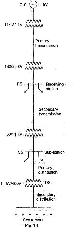
1.Generating station: In Fig 7.1, G.S. represents the generating station where electric power is produced by 3-phase alternators operating in parallel. The usual generation voltage is 11 kV. For economy in the transmission of electric power, the generation voltage (i.e., 11 kV) is stepped upto 132 kV (or more) at the generating station with the help of 3-phase transformers. The transmission of electric power at high voltages has several advantages including the saving of conductor material and high transmission efficiency. It may appear advisable to use the highest possible voltage for transmission of electric power to save conductor material and have other advantages. But there is a limit to which this voltage can be increased. It is because increase in transmission voltage introduces insulation problems as well as the cost of switchgear and transformer equipment is increased. Therefore, the choice of proper transmission voltage is essentially a question of economics. Generally the primary transmission is carried at 66 kV, 132 kV, 220 kV or 400 kV.
2.Primary transmission: The electric power at 132 kV is transmitted by 3-phase, 3-wire overhead system to the outskirts of the city. This forms the primary transmission.
3.Secondary transmission: The primary transmission line terminates at the receiving station (RS) which usually lies at the outskirts of the city. At the receiving station, the voltage is re duced to 33kV by step-down transformers. From this station, electric power is transmitted at 33kV by 3-phase, 3-wire over¬head system to various sub-stations (SS) located at the strategic points in the city. This forms the secondary transmission. Fig. 7.2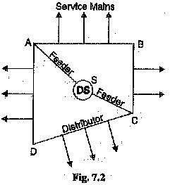
4.Primary distribution: The secondary transmission line terminates at the sub-station (SS) where voltage is reduced from 33 kV to 11kV, 3-phase, 3-wire. The 11 kV lines run along the important road sides of the city. This forms the primary distribution. It may be noted that big con-sumers (having demand more than 50 kW)are generally supplied power at 11 kV for further handling with their own sub-stations.
5.Secondary distribution: The electric power from primary distribution line (11 kV) is delivered to distribution sub-stations (DS). These sub-stations are located near the consumers localities and step down the voltage to 400 V, 3-phase, 4-wire for secondary distribution. The voltage between any two phases is 400 V and between any phase and neutral is 230 V The single-phase residential lighting load is connected between any one phase and neutral, whereas 3-phase, 400 V motor load is connected across 3-phase lines directly.
It may be worthwhile to mention here that secondary distribution system consists of feeders, distributors and service mains. Fig. 7.2 shows the elements of low voltage distribution system. Feeders (SC or SA) radiating from the distribution sub-station (DS) Electric Supply power to the distributors (AB, BC, CD and AD). No consumer is given direct connection from the feeders. Instead, the consumers are connected to the distributors through their service mains.
Note. A practical power system has large number of auxiliary equipments (e.g., fuses, circuit breakers, voltage control devices etc.). However, such equipments are not shown in Fig. 7.1. It is because the amount of information included in the diagram depends on the purpose for which the diagram is intended. Here our purpose is to display general lay out of the power system. Therefore, the location of circuit breakers, relays etc., is unimportant.
Further, the structure of power system is shown by a single line diagram. The complete 3-phase circuit is seldom necessary to convey even the most detailed information about the system. In fact, the complete diagram is more likely to hide than to clarify the information we are seeking from the system viewpoint.