Electric Stress Control:
The Electric Stress Control distribution is usually governed by the Poisson’s equation: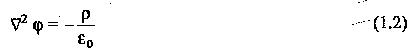
where φ is the potential at a given point, ρ is the space charge density in the region, and ε0 is the electric permittivity of free space (vacuum). However, in most of the high voltage apparatus, space charges are not normally present, and hence the potential distribution is governed by the Laplace’s equation:
![]()
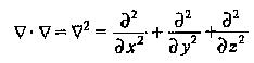
In Eqs (1.2) and (1.3) the operator ∇2 is called the Laplacian and is a vector with properties
There are many methods available for determining the potential distribution. The most commonly used methods are
- the electrolytic tank method, and
- the numerical methods
The potential distribution can also be calculated directly. However, this is very difficult except for simple geometries. In many practical cases, a good understanding of the problem is possible by using some simple rules to plot the field lines and equipotentials. The important rules are
- the equipotentials cut the field lines at right angles,
- when the equipotentials and field lines are drawn to form curvilinear squares, the density of the field lines is an indication of the Electric Stress Control in a given region, and
- in any region, the maximum electric field is given by dv∕dx, where dv is the voltage difference between two successive equipotentials, dx apart.
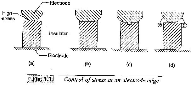
Considerable amount of labour and time can be saved by properly choosing the planes of symmetry and shaping the electrodes accordingly. Once the voltage distribution of a given geometry is established, it is easy to refashion or redesign the electrodes to minimize the stresses so that the onset of corona is prevented. This is a case normally encountered in high voltage electrodes of the bushings, standard capacitors, etc. When two dielectrics of widely different permittivities are in series, the Electric Stress Control is very much higher in the medium of lower permittivity. Considering a solid insulation in a gas medium, the stress in the gas becomes εr times that in the solid dielectric, where εr is the relative permittivity of the solid dielectric. This enhanced stress occurs at the electrode edges and one method of overcoming this is to increase the electrode diameter. Other methods of Electric Stress Control are shown in Fig. 1.1.
In the design of high voltage apparatus, the electric field intensities have to be controlled, otherwise higher stresses will trigger or accelerate the aging of the insulation leading to its failure. Over the years, many methods for controlling and optimizing electric fields to get the most economical designs have been developed. Electric field control methods form an important component of the overall design of equipment.
1.Electric Field
A brief review of the concepts of electric fields is presented, as it is essential for high voltage engineers to have a knowledge of the field intensities in various media under electric stresses. It also helps in choosing proper electrode configurations and economical dimensioning of the insulation, such that highly stressed regions are not formed and reliable operation of the equipment results in its anticipated life.
The field intensity E at any location in an electrostatic field is the ratio of the force on an infinitely small charge at that location to the charge itself as the charge decreases to zero. The force F on any charge q at that point in the field is given by![]()
The electric flux density D associated with the field intensity E is
![]()
where E is the permittivity of the medium in which the electric field exists. The work done on a charge when moved in an electric field is defined as the potential. The potential φ is equal to
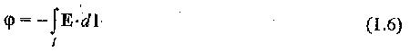
where l is the path through which the charge is moved.
Several relationships between the various quantities in the electric field can be summarized as follows:
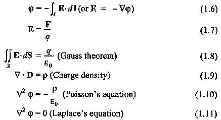
where F is the force exerted on a charge q in the electric field E, and S is the closed surface containing charge q.
2.Uniform and Non-Uniform Electric Fields
In general, the electric fields between any two electrodes can be either uniform and non-uniform. In a uniform field gap, the average field E is the same throughout the field rigion, whereas in a non-uniform field gap, E is different at different points of the field region.
Uniform or approximately uniform field distributions exist between two infinite parallel plates or two spheres of equal diameters when the gap distance is less than diameter of the sphere. Spherical electrodes are frequently used for high voltage measurements and for triggering in impulse voltage generation circuits. Sometimes, parallel plates of finite size are used to simulate uniform electric fields, when gap separation is much smaller than plate size.
In the absence of space charges, the average field E in a non-uniform field gap is maximum at the surface of the conductor which has the smallest radius of curvature. It has the minimum field E at the conductor having the large radius of curvature. In this case, the field is not only non-uniform but also asymmetrical. Most of the practical high voltage components used in electric power systems normally have non-uniform and asymmetrical field distribution.
3.Estimation of Electric Field in Some Geometric Boundaries
It has been shown that the maximum electric field Em in a given electric field configuration is of importance. The mean electric field over a distance d between two conductors with a potential difference of V12 is
![]()