Dual Slope Integrating Type DVM (Voltage to Time Conversion):
Dual Slope Integrating Type DVM – In ramp techniques, superimposed noise can cause large errors. In the dual ramp technique, noise is averaged out by the positive and negative ramps using the process of integration.
Principle of Dual Slope Type DVM:
As illustrated in Fig. 5.3, the input voltage ’ei’ is integrated, with the slope of the integrator output proportional to the test input voltage. After a fixed time,
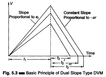
equal to t1, the input voltage is disconnected and the integrator input is connected to a negative voltage – er The integrator output will have a negative slope which is constant and proportional to the magnitude of the input voltage. The block diagram is given in Fig. 5.4.
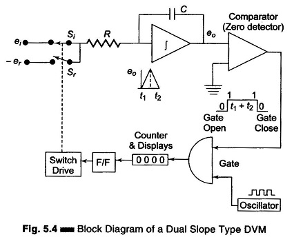
At the start a pulse resets the counter and the F/F output to logic level ‘0’. Si is closed and Sr is open. The capacitor begins to charge. As soon as the integrator output exceeds zero, the comparator output voltage changes state, which opens the gate so that the oscillator clock pulses are fed to the counter. (When the ramp voltage starts, the comparator goes to state 1, the gate opens and clock pulse drives the counter.) When the counter reaches maximum count,
i.e. the counter is made to run for a time ‘t1‘ in this case 9999, on the next clock pulse all digits go to 0000 and the counter activates the F/F to logic level ‘1’. This activates the switch drive, ei is disconnected and –er is connected to the integrator. The integrator output will have a negative slope which is constant, i.e. integrator output now decreases linearly to 0 volts. Comparator output state changes again and locks the gate. The discharge time t2 is now proportional to the input voltage. The counter indicates the count during time t2. When the negative slope of the integrator reaches zero, the comparator switches to state 0 and the gate closes, i.e. the capacitor C is now discharged with a constant slope. As soon as the comparator input (zero detector) finds that eo, is zero, the counter is stopped. The pulses counted by the counter thus have a direct relation with the input voltage.
During charging

During discharging

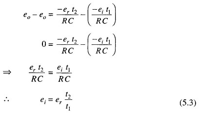
Subtracting Eqs 5.2 from 5.1 we have
If the oscillator period equals T and the digital counter indicates n1 and n2 counts respectively,

Now, n1 and er are constants.
Let

From Eq. 5.3 it is evident that the accuracy of the measured voltage is independent of the integrator time constant. The times t1 and t2 are measured by the count of the clock given by the numbers n1 and n2 respectively. The clock oscillator period equals T and if n1 and er are constants, then Eq. 5.4 indicates that the accuracy of the method is also independent of the oscillator frequency.
The dual slope technique has excellent noise rejection because noise and superimposed ac are averaged out in the process of integration. The speed and accuracy are readily varied according to specific requirements; also an accuracy of ± 0.05% in 100 ms is available.