Dissipation Factor in Schering Bridge:
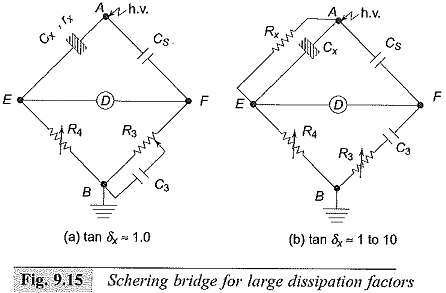
Extension of range of the Dissipation Factor in Schering Bridge can be achieved by connecting in parallel an additional large capacitance across C3. But to avoid expensive and large-size decade capacitances the C3R3 arm is modified as shown in Fig. 9.15a. R3 is made as a slide wire along with decade resistance, and C3 is extended by connecting a single fixed capacitor. Usually the modification is limited to tan δ ≈ 1.0.
For tan δ values greater than 1.0 and in the range 1 to 10 or greater, the C3R3 arm is no longer made a parallel combination. Instead, it is made a series combination of C3 and R3 where R3 is variable. This makes the test object to be an equivalent of Cx in parallel with Rx a better approximation for the capacitors and dielectrics. With this modification, tan δ range is made wider, from 10-4 to values greater than 10. The arrangement is shown in Fig. 9.15b.
Schering Bridge for High Charging Currents:
High capacitance test objects, such as high voltage power cables and power factor correction capacitors take high charging currents which may exceed the rating of the variable resistance R4 (Fig. 9.1 1 ). Further, the value of the resistance R4 will become so low that the contact resistances and residual inductances can no longer be neglected. For these cases, the range is increased by connecting a shunting resistor Rs in parallel across R4 as shown in Fig. 9.14.
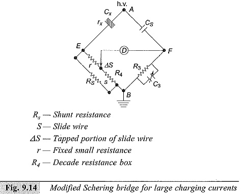
Hence, the balance conditions are modified as
where,
Rs = shunt resistance,
r = a small resistance added in the first arm,
S = slide wire resistance
R4 = the decade variable resistor, and
ΔS = portion of the slide wire resistance.
Usually Rs, the shunt resistance is kept outside, and special arrangements are made for the correction of its inductive phase angle error, if necessary.
Schering Bridge for Audio Frequency Range (50 Hz to 100 kHz):
The capacitance bridge used for dielectric measurements is shown in Fig. 9.16, where CARA and CBRB are the ratio arm capacitances. Substitution method is preferred in this range for greater accuracy. The specimen is connected across the standard variable capacitance CN. The bridge is balanced with and without the dielectric specimen CX. The specimen capacitance connected (CX) is the difference of the two readings of the standard capacitor CN.
![]()
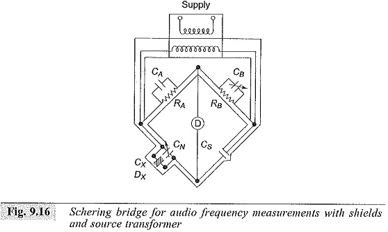
The balance for the loss factor (resistive component balance) may be done in any one of the following ways:
- a small variable resistance in series with the standard capacitor CN,
- a variable resistor of high value in parallel with Cs, and
- a variable capacitor in parallel with RB (CB variation).
Of these three, the third method is normally used, as CB can be made a variable air capacitor of high quality and the errors that arise within the resistances at high frequencies (skin effect, etc.) are avoided. The Dissipation Factor in Schering Bridge tan δ for the third method is given as,
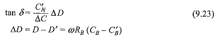
Usually, the total capacitance CN in the variable arm is made small to get a large variation in ΔD.
Whenever the specimen capacitance is greater than that of the maximum value of CN, the substitution method is not possible. In such cases, direct measurement without CN is done. The expreSsions, in the case of a direct measurement for Cx and tan δ are:
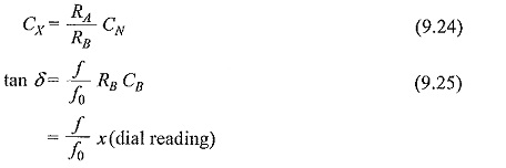
where f0 is the calibration frequency.
The range of this bridge extends from 1 pF to about 1000 pF when the substitution method is used, from 1000 pF to 100 nF when the direct method is used.