Display Methods in Radar System:
The output of a radar receiver may be displayed in any of a number of ways, the following three being the most common Display Methods in Radar System are: Deflection Modulation of a cathode-ray-tube screen as in the A scope, Intensity Modulation of a CRT as in the Plan-Position Indicator (PPI) or direct feeding to a computer. Additional information, such as height, speed or velocity, may be shown on separate displays.
A Scope:
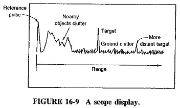
As can be seen from Figure 16-9, the operation of this display system is rather similar to that of an ordinary oscilloscope. A sweep waveform is applied to the horizontal deflection plates of the CRT and moves the beam slowly from left to right across the face of the tube, and then back to the starting point. The flyback period is rapid and occurs with the beam blanked out. In the absence of any received signal, the display is simply a horizontal straight line, as with oscilloscopes. The demodulated receiver output is applied to the vertical deflection plates and causes the departures from the horizontal line, as seen in Figure 16-9. The horizontal deflection sawtooth waveform is synchronised with the transmitted pulses, so that the width of the CRT screen corresponds to the time interval between successive pulses. Displacement from the left-hand side of the CRT corresponds to the range of the target. The first “blip” is due to the transmitted pulse, part of which is deliberately applied.to the CRT for reference. Then come various strong blips due to reflections from the ground and nearby objects, followed by noise, which is here called Ground Clutter (the name is very descriptive, although the pips due to noise are not constant in amplitude or position). The various targets then show up as (ideally) large blips, again interspersed with grass. The height of each blip corresponds to the strength of the returned echo, while its distance from the reference blip is a measure of its range. This is why the blips on the right of the screen have been shown smaller than those nearer to the left. It would take a very large target indeed at a range of 40 km to produce the same size of echo as a normal target only 5 km away!
Of the various indications and controls for the A scope, perhaps the most important is the range calibration, shown horizontally across the tube. In some Display Methods in Radar System only one may be shown, corresponding to a fixed value of 1 km per cm of screen deflection, although in others several scales may be available, with suitable switching for more accurate range determination of closer targets. It is possible to expand any section of the scan to allow more accurate indication of that particular area (this is rather similar to bandspread in communications receivers). It is also often possible to introduce pips derived from the transmitted pulse, which have been passed through a time-delay network. The delay is adjustable, so that the marker blip can be made to coincide with the target. The distance reading provided by the marker control is more accurate than could have been estimated from a direct reading of the CRT. A gain control for vertical deflection is provided, which allows the sensitivity to be increased for weak echoes or reduced for strong ones. In the case of strong signals, reducing the sensitivity will reduce the amplitude of the ground clutter.
By its very nature, the A scope presentation is more suitable for use with tracking than with search antennas, since the echoes returned from one direction only are displayed; the antenna direction is generally indicated elsewhere.
Plan Position Indicator:
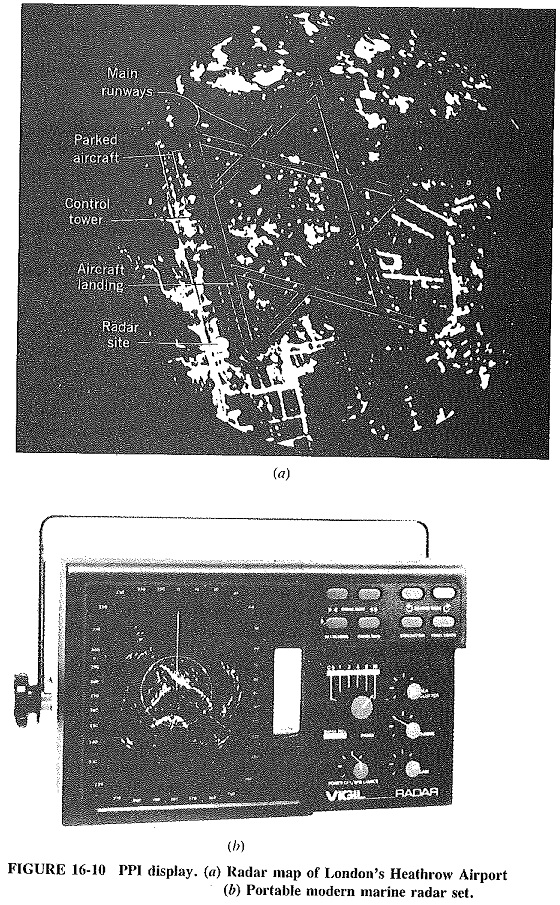
As shown in Figure 16-10, the PPI display shows a map of the target area. The CRT is now intensity-modulated, so that the signal from the receiver after demodulation is applied to the grid of the cathode-ray tube. The CRT is biased slightly beyond cutoff, and only blips corresponding to targets permit beam current and therefore screen brightness. The scanning waveform is now applied to a pair of coils on opposite sides of the neck of the tube, so that magnetic deflection is used, and a sawtooth current is required. The coils, situated in a yoke similar in appearance to that around the neck of a television picture tube, are rotated mechanically at the same angular velocity as the antenna. Hence the beam is not only deflected radially outward from the center and then back again rapidly but also rotates continuously around the tube. The brightness at any point on the screen indicates the presence of an object there, with its position corresponding to its actual physical position and its range being measured radially out from the center.
Long-persistence phosphors are normally used to ensure that the face of the PPI screen does not flicker. It must be remembered that the scanning speed is rather low compared to the 60 fields per second used with television, so that various portions of the screen could go dim between successive scans. The resolution on the screen depends on the beamwidth of the antenna, the pulse length, the transmitted frequency, and even on the diameter of the CRT beam. Circular screens are used with diameters ranging up to 40 cm, but 30 cm is most often used.
The PPI display lends itself to use with search Display Methods in Radar System and is particularly suitable when conical scanning is employed. Note should also be taken of the fact that distortion of true map positions will take place if PPI is used on an aircraft, and its antenna does not point straight down. The range then seen on the screen is called the slant range. If the antenna of a mapping radar points straight down from the aircraft body, but the aircraft is climbing, the terrain behind will appear shortened, while the area ahead is distorted by being lengthened. If required, computer processing may be used to correct for radar attitude, therefore converting slant range into true range.
It should be noted that the mechanics of generating the appropriate waveforms and scanning the radar CRT are similar to those functions in TV receivers.
Automatic Target Detection:
The performance of Display Methods in Radar System operators may be erratic or inaccurate (people staring at screens for long hours do get tired); therefore the output of the radar receiver may be used in a number of ways that do not involve human operators. One such system may involve computer processing and simplification of the received data prior to display on the radar screen. Other systems use analog computers for the reception and interpretation of the received data, together with automatic tracking and gun laying (or missile pointing).