Direct Digital Control:
Developments in digital electronics have led to many industrial processes being computer controlled. The first system used was Direct Digital Control (DDC), in which a computer measured each variable in the process, these signals being used to maintain the required set points in the process.
As digital electronics developed, minicomputers become more competitive, and with the advent of electronic Multiplexer (Mux) and Demultiplexer (Demux), it is possible to sample the state of many analog and digital transducers at high speed and also to control many values or devices in the plant.
A basic Direct Digital Control System is shown in Fig. 21.18. In this system a large number of transducers are sited around the plant, each transducer being connected to one input of a Mux. ( A Mux can be considered as- the electronic equivalent of a switch with a contact or blade which rotates very rapidly so that it moves from one transducer to another, the blade remaining in contact with the transducer long enough for an ADC to sample and digitise or to quantise the analog signal. The quantised data are then transmitted along the data bus of the system to the CPU).
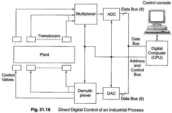
When the CPU has analysed the data from one or more transducers and has compared them with the appropriate set points in the computer program, it sends signals along the data bus to the values controlling the system as follows. The digital signal produced by the CPU is converted into an analog signal by a DAC and the analog signal is transmitted to the appropriate control value through a demux. As this is being performed, data are displayed on the operator’s visual display unit and if necessary, he can remotely change the set points associated with various sections of the process.
Computer Supervisory Control System:
An alternative control system known as Computer Supervisory Control (CSC) is used in microprocessor based systems. In this case, the process is controlled by a number of local feedback loops using individual process controllers, the main computer merely acting in a supervisory role in which it monitors the measured variable (although it has the capability of remotely controlling set points of the controllers). This method provides the local operator with his own controller.
A basic Computer Supervisory Control system is shown in Fig. 21.19. Each digital control controls one section of the plant by means of a closed loop involving its own sensors and control values. Each controller can either be operated manually to give the local operator complete control of his own section of the plant or it can be remotely controlled by the computer operator.
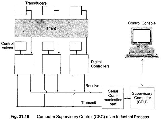
The computer is connected to each controller by means of a communication port which allows the computer either to receive information from the process controllers or to transmit data to the controllers to change, say, a set point. To minimise the cost of cabling, the communication port operates in a serial mode, that is, the data are sent along the communicating link in the form of pulses (which requires only two wires — a “send” wire and a “receive” wire). This method is clearly more economical than using a 8-bit data bus throughout the plant, but it is slower in operation, since it takes more time to send eight individual bits along one wire then it takes to send 8-bits simultaneously along eight wires. The digital process controller (also called the central computer) must contain a special interface which converts the pulses it receives in a serial mode along the supervisory serial data bus into the parallel mode used in microprocessor chip itself. Such an interface is known as a UART (Universal Asynchronous Receiver/Transmitter).