Differential Relay:
Most of the relays discussed so far relied on excess of current for their operation. Such relays are less sensitive because they cannot make correct distinction between heavy load conditions and minor fault conditions. In order to overcome this difficulty, differential relay are used.
A differential relay is one that operates when the phasor difference of two or more similar electrical quantities exceeds a pre-determined value.
Thus a current differential relay is one that compares the current entering a section of the system with the current leaving the section. Under normal operating conditions, the two currents are equal but as soon as a fault occurs, this condition no longer applies. The difference between the incoming and outgoing currents is arranged to flow through the operating coil of the relay. If this differential current is equal to or greater than the pickup value, the relay will operate and open the circuit breaker to isolate the faulty section.
It may be noted that almost any type of relay when connected in a particular way can be made to operate as a differential relay. In other words, it is not so much the relay construction as the way the relay is connected in a circuit that makes it a differential relay. There are two fundamental systems of differential or balanced protection viz.
- Current balance protection
- Voltage balance protection
Current Differential Relay:
Fig. 21.23 shows an arrangement of an over current relay connected to operate as a differential relay. A pair of identical current transformers are fitted on either end of the section to be protected (alternator winding in this case). The secondaries of CT’s are connected in series in such a way that they carry the induced currents in the same direction. The operating coil of the over current relay is connected across the CT secondary circuit. This differential relay compares the current at the two ends of the alternator winding.
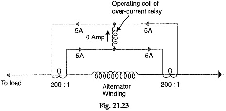
Under normal operating conditions, suppose the alternator winding carries a normal current of 1000 A. Then the currents in the two secondaries of CT’s are equal [See Fig. 21.23]. These currents will merely circulate between the two CT’s and no current will flow through the differential relay. Therefore, the relay remains inoperative. If a ground fault occurs on the alternator winding as shown in Fig. 21.24 (i), the two secondary currents will not be equal and the current flows through the operating coil of the relay, causing the relay to operate. The amount of current flow through the relay will depend upon the way the fault is being fed.
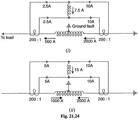
(i) If some current (500 A in this case) flows out of one side while a larger current (2000 A) enters the other side as shown in Fig. 21.24 (i), then the difference of the CT secondary currents i.e. 10 – 2 5 = 7.5 A will flow through the relay.
(ii) If current flows to the fault from both sides as shown in Fig. 21.24 (ii), then sum of CT secondary currents i.e. 10 + 5 = 15 A will flow through the relay.
Disadvantages of Current Differential Relay:
- The impedance of the pilot cables generally causes a slight difference between the currents at the two ends of the section to be protected. If the relay is very sensitive, then the small differential current flowing through the relay may cause it to operate even under no fault
- Pilot cable capacitance causes incorrect operation of the relay when a large through-current
- Accurate matching of current transformers cannot be achieved due to pilot circuit impedance.
The above disadvantages are overcome to a great extent in biased beam relay.
Biased Beam Relay:
The biased beam relay (also called Percentage Differential Relay) is designed to respond to the differential current in terms of its fractional relation to the current flowing through the protected section. Fig. 21.25 shows the schematic arrangement of a biased beam relay. It is essentially an overcurrent balanced beam relay type with an additional restraining coil. The restraining coil produces a bias force in the opposite direction to the operating force.
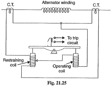
Under normal and through load conditions, the bias force due to restraining coil is greater than the operating force. Therefore, the relay remains inoperative. When an internal fault occurs, the operating force exceeds the bias force. Consequently, the trip contacts are closed to open the circuit breaker. The bias force can be adjusted by varying the number of turns on the restraining coil.
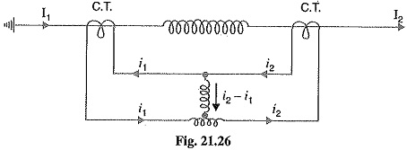
The biased beam relay equivalent circuit diagram is shown in Fig. 21.26. The differential current in the operating coil is proportional to i2 — i1 and the equivalent current in the restraining coil is proportional to (i1 + i2)/2 since the operating coil is connected to the mid-point of the restraining coil. It is clear that greater the current flowing through the restraining coil, the higher the value of current required in the operating winding to trip the relay. Thus under a heavy load, a greater differential current through the relay operating coil is required for operation than under light load conditions. This relay is called Percentage Relay because the operating current required to trip can be expressed as a percentage of load current.
Voltage Balance Differential Relay:
Fig. 21.27 shows the arrangement of voltage balance protection. In this scheme of protection, two similar current transformers are connected at either end of the element to be protected (e.g. an alternator winding) by means of pilot wires. The secondaries of current transformers are connected in series with a relay in such way that under normal conditions,their induced e.m.f.s’ are in opposition.
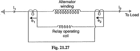
Under healthy conditions, equal currents II = I2) flow in both primary windings. Therefore, the secondary voltages of the two transformers are balanced against each other and no current will flow through the relay operating coil. When a fault occurs in the protected zone, the currents in the two primaries will differ from one another (i.e. I1 ≠ I2) and their secondary voltages will no longer be in balance. This voltage difference will cause a current to flow through the operating coil of the relay which closes the trip circuit.
Disadvantages in Voltage Balance Differential Relay:
The voltage balance system suffers from the following drawbacks:
- A multi-gap transformer constriction is required to achieve the accurate balance between current transformer pairs.
- The system is suitable for protection of cables of relatively short lengths due to the capacitance of pilot wires. On long, cables, the charging current may be sufficient to operate the relay even if a perfect balance of current transformers is attained.
The above disadvantages have been overcome in Translay (modified) balanced voltage system.