Differential Protection of Alternators:
The most common system used for the protection of stator winding faults employs circulating-current principle (Refer back to Art. 21.18). In this scheme of Differential Protection of Alternators, currents at the two ends of the protected section are compared. Under normal operating conditions, these currents are equal but may become unequal on the occurrence of a fault in the protected section. The difference of the currents under fault conditions is arranged to pass through the operating coil of the relay. The relay then closes its contacts to isolate protected section from the system. This form of protection is also known as Merz-Price Circulating Current Scheme.
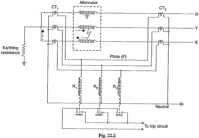
Schematic arrangement: Fig. 22.2 shows the schematic arrangement of Differential Protection of Alternators for a 3-phase alternator. Identical current transformer pairs CT1 and CT2 are placed on either side of each phase of the stator windings. The secondaries of each set of current transformers are connected in star ; the two neutral points and the corresponding terminals of the two star groups being connected together by means of a four-core pilot cable. Thus there is an independent path for the currents circulating in each pair of current transformers and the corresponding pilot P.
The relay coils are connected in star, the neutral point being connected to the current-transformer common neutral and the outer ends one to each of the other three pilots. In order that burden on each current transformer is the same, the relays are connected across equipotential points of the three pilot wires and these equipotential points would naturally be located at the middle of the pilot wires. The relays are generally of electromagnetic type and are arranged for instantaneous action since fault should be cleared as quickly as possible.
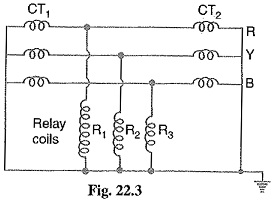
Operation: Referring to Fig. 22.2, it is clear that the relays are connected in shunt across each circulating path. Therefore, the circuit of Fig. 22.2 can be shown in a simpler form in Fig. 22.3. Under normal operating conditions, the current at both ends of each winding will be equal and hence the currents in the secondaries of two CTs connected in any phase will also be equal. Therefore, there is balanced circulating current in the pilot wires and no current flows through the operating coils (R1, R2 and R3) of the relays. When an earth-fault or phase-to-phase fault occurs, this condition no longer holds good and the differential current flowing through the relay circuit operates the relay to trip the circuit breaker.
(i) Suppose an earth fault occurs on phase R due to breakdown of its insulation to earth as shown in Fig. 22.2. The current in the affected phase winding will flow through the core and frame of the machine to earth, the circuit being completed through the neutral earthing resistance. The currents in the secondaries of the two CTs in phase R will become unequal and the difference of the two currents will flow through the corresponding relay coil (i.e. R1), returning via the neutral pilot. Consequently, the relay operates to trip the circuit breaker.
(ii) Imagine that now a short-circuit fault occurs between the phases Y and B as shown in Fig. 22.2. The short-circuit current circulates via the neutral end connection through the two windings and through the fault as shown by the dotted arrows. The currents in the secondaries of two CTs in each affected phase will become unequal and the differential current will flow through the operating coils of the relays (i.e. R2 and R3) connected in these phases. The relay then closes its contacts to trip the circuit breaker.
It may be noted that the relay circuit is so arranged that its energizing causes (i) opening of the breaker connecting the alternator to the bus-bars and (ii) opening of the field circuit of the alternator.
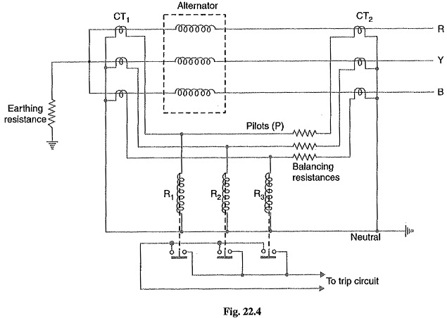
It is a prevailing practice to mount current transformers CT1 in the neutral connections (usually in the alternator pit) and current transformers CT2 in the switch-gear equipment. In some cases, the alternator is located at a considerable distance from the switchgear. As the relays are located close to the circuit breaker, therefore, it is not convenient to connect the relay coils to the actual physical midpoints of the pilots, Under these circumstances, balancing resistances are inserted in the shorter lengths of the pilots so that the relay tapping points divide the whole secondary impedance of two sets of CTs into equal portions. This arrangement is shown in Fig. 22.4. These resistances are usually adjustable in order to obtain the exact balance.
Limitations: The two circuits for alternator protection shown above have their own limitations. It is a general practice to use neutral earthing resistance in order to limit the destructive effects of earth-fault currents. In such a situation, it is impossible to protect whole of the stator windings of a star-connected alternator during earth-faults. When an earth-fault occurs near the neutral point, there may be insufficient voltage across the short-circuited portion to drive the necessary current round the fault circuit to operate the relay. The magnitude of unprotected zone depends upon the value of earthing resistance and relay setting.
Makers of protective gear speak of “protecting 80% of the winding” which means that faults in the 20% of the winding near the neutral point cannot cause tripping i.e. this portion is unprotected. It is a usual practice to protect only 85% of the winding because the chances of an earth fault occurring near the neutral point are very rare due to the uniform insulation of the winding throughout.
Modified Differential Protection for Alternators:
If the neutral point of a star-connected alternator is earthed through a high resistance, Modified Differential Protection of Alternators schemes shown in Fig. 22.2 or 22.4 will not provide sufficient sensitivity for earth-faults. It is because the high earthing resistance will limit the earth-fault currents to a low value, necessitating relays with low current settings if adequate portion of the generator winding is to be protected. However, too low a relay setting is undesirable for reliable stability on heavy through phase-faults. In order to overcome this difficulty, a modified form of differential protection is used in which the setting of earth faults is reduced without impairing stability.
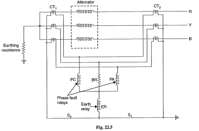
The modified arrangement is shown in Fig. 22.5. The modifications affect only the relay connections and consist in connecting two relays for phase-fault protection and the third for earth-fault protection only. The two phase elements (PC and PA) and balancing resistance (BR) are connected in star and the earth relay (ER) is connected between this star point and the fourth wire of circulating current pilot-circuit.
Operation: Under normal operating conditions, currents at the two ends of each stator winding will be equal. Therefore, there is a balanced circulating current in the phase pilot wires and no current flows through the operating coils of the relays. Consequently, the relays remain inoperative.
If an earth-fault occurs on any one phase, the out-of-balance secondary current in CTs in that phase will flow through the earth relay ER and via pilot S1 or S2 to the neutral of the current transformers. This will cause the operation of earth relay only. If a fault occurs between two phases, the out of balance current will circulate round the two transformer secondaries via any two of the coils PA, BR, PC (the pair being decided by the two phases that are faulty) without passing though the earth relay ER. Therefore, only the phase-fault relays will operate.