Current Source Inverter Fed Induction Motor Drive:
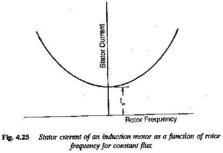
Current Source Inverter Fed Induction Motor Drive – In a voltage source inverter fed induction motor the applied voltage to the stator is proportional to the frequency, with a correction for the stator resistance drop, particularly at low speeds, to keep the flux constant. It is a very well known fact that the current drawn by an induction motor does not depend on the stator frequency when the air gap flux is constant. There exists a fixed relationship between the slip frequency and stator current for rated flux in the air gap, as shown in Fig. 4.25. By controlling the slip of the motor, the stator current can be controlled. An indirect flux control is therefore possible. The control is simpler than voltage control. The curve between slip frequency and stator current can be calculated using the equivalent circuit. A PWM inverter can be controlled to provide the desired currents in the motor.
In a dc link converter, if the dc link current is controlled the inverter is called a current source inverter. The current in the dc link is kept constant by a high inductance and the capacitance of the filter is dispensed with. The variable dc link voltage is converted to a Current Source Inverter Fed Induction Motor by means of the inductance. The dc supply is of high impedance. As the link current is held constant, the output current waveform is determined by the operation of the inverter, while the output voltage is determined by the nature of the load impedance. A Current Source Inverter Fed Induction Motor is suitable for loads which present a low impedance to harmonic currents and have unity p.f.
A Current Source Inverter Fed Induction Motor has a very simple configuration. No feedback diodes are required. A phase controlled rectifier is used on the line side to provide a current control. As the dc link contains only the inductance, regeneration is possible by changing the polarity of voltages and maintaining the current direction. Hence, a four quadrant drive is simple and straightforward. It provides effective buffering of the inverter output from supply voltage variations. Direct control of stator current allows a precise closed loop control to be implemented with relative ease.
The commutation of the inverter is load dependent. The load parameters form a part of the commutation circuit. A matching is therefore required between the inverter and the motor. Multimotor operation is not possible. The inverter must necessarily be a force commutated one, as the induction motor cannot provide the reactive power for the inverter.
The constant dc link current is allowed to flow through the phases of the motor by control of the inverter, and therefore the motor current is a quasi-square wave. The motor voltage is almost sinusoidal with superimposed spikes, due to commutation. These voltage spikes decide the voltage rating of the thvristors and also affect the insulation of the motor. These spikes can be limited if the machine has small leakage reactance or if the commutating capacitors are large. A machine with smaller leakage reactance is suitable for Current Source Inverter Fed Induction Motor operation to keep the voltage spikes and the harmonic losses to a minimum. The effect of torque pulsations decreases and the frequency of operation can be increased. The commutating capacitance is chosen to strike a compromise between voltage spikes and the highest operating frequency. The commutation requires a definite minimum current. The inverter has the ability to recover from commutation failure. The link inductance causes a slow rise of the fault current and by the time it reaches high values, the fault may be cleared.
The drive poses stability problems at light loads. Open loop operation is not possible. It has a very wide range of speed control but dynamic performance is poor.
The drive motor requires derating due to harmonic losses and associated heating. Torque pulsations are present and their amplitude is large at low frequency of operation, due to additional harmonics in the rotor flux. The line power factor is poor, due to phase control.
Up to the rated frequency, the drive is in a constant torque mode and above the rated frequency the drive is in a constant horse power mode.
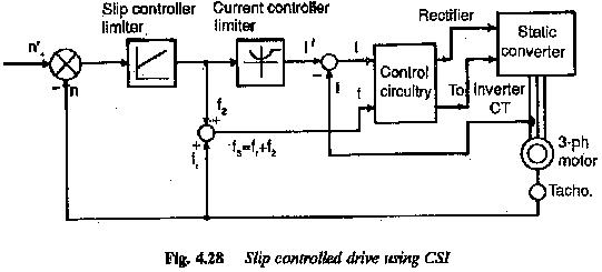
The stator current of an induction motor operating on a variable frequency, variable voltage supply is independent of stator frequency if the airgap flux is maintained constant. However, it is a function of the rotor frequency. The torque developed is also a function of rotor frequency only. Using these features a slip controlled drive (Fig. 4.28) can be developed employing a current source inverter to feed an induction motor. The relationship between the rotor frequency and stator current for rated flux in the airgap is introduced in the control. Thus an indirect control of flux is possible. The output of the function generator gives the reference value of current. The measured current is compared with the reference value and the error is used to alter the firing angle of the phase controlled converter on the line side. The input to the function generator is the difference between the reference speed and actual speed and it can be considered as slip frequency which is added to the frequency corresponding to rotor speed This gives the value of stator frequency and the machine side inverter is controlled to give this frequency. The control is operative until the rotor attains the desired speed with the required slip frequency.
The slip controlled drive has the following advantages:
1.Controlled slip drive is highly efficient.
2.Precise control of torque is possible over a wide speed range.
3.The slip frequency can be any value up to the value corresponding to breakdown torque. The operation is at a very good power factor. The operation is very stable.
4.The rotor can be accelerated at constant torque and current maintaining the rotor frequency at a suitable value. Fast acceleration.
5.As this leads to soft starting the motor does not see the blocked rotor currents and the associated voltage slips are not there.
6.Special rotors with high starting torque are not necessary. Rotors with low resistance may be used so that the losses are limited.
7.Regenerative braking can be incorporated. Braking at constant torque is possible.
8.The drive has efficiency comparable to a thyristorized dc drive.
The added advantages of squirrel cage induction motors like high power to weight ratio, less maintenance, low inertia, no limitations on the power ranges and speed ranges make slip controlled drive a real competitor to dc motor drives.
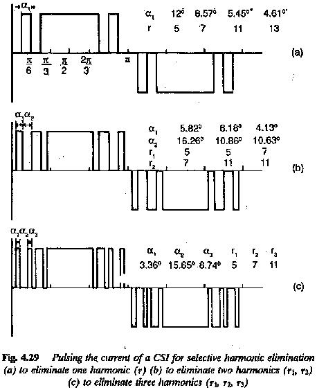
Selected harmonic elimination methods or PWM principles can be employed to reduce the effects of torque pulsations, particularly at low speeds. In these methods control can be achieved by controlling the dc link current and PWM principle can then be used solely to control the harmonic content of the current waveform. This separation of the current and harmonic control functions allows the choice of PWM control strategy being directed solely towards improving the motor torque pulsations and reducing the harmonic losses.
The majority of PWM strategies for a Current Source Inverter Fed Induction Motor are based on selected harmonic elimination techniques. They are used to eliminate the lower order harmonics from the stator current and the methods result in the elimination of lower order torque ripples (Fig. 4.29).
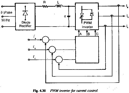
In recent years PWM strategies have been specially developed to minimise the rotor speed ripple due to torque pulsation, to result in a drive having smooth rotation at low speeds (Fig. 4.30).
The general features of Current Source Inverter Fed Induction Motor can be summarised as follows:
1.Load dependent commutation: As the load parameters form part of the commutation circuit, the inverter and motor must be matched.
2.The inverter has a simple configuration. FWD’s are absent.
3.Only single motor operation
4.The dc link contains only inductance. To maintain constant current this has to be very large. Two quadrant operation is straightforward
5.Invariably, a phase controlled rectifier is required on the line side. The variable dc link voltage is converted to a constant current source by means of high link inductance.
6.The inverter is force commutated to give variable frequency currents to feed the motor.
7.The value of the capacitance is a compromise between the voltage spikes and highest operating frequency. Larger the capacitance smaller the voltage The highest operating frequency is also limited.
8.The leakage reactance of the motor influences the harmonic voltages. It is also responsible for spikes of voltage during commutation. The leakage reactance being a parameter of the commutation circuit, determines the time of commutation, and consequently the upper operational frequency is limited. A motor must have smaller leakage reactance to have reduced harmonic voltages and spikes of voltage and to increase the range of speed control. The spikes influence the rating of the thyristor and affect the insulation. The motor size becomes larger if leakage reactance is small.
9.Converter grade thyristors are sufficient. Thyristor utilisation is good
10.The inverter recovers from commutation failure. The link inductance causes a slow rise of fault current and by the time it reaches high value it can be suppressed.
11.There is a stability problem at light load. A minimum current should be there for commutation.
12.Open loop operation is not possible. Dynamic response is sluggish
13.The line p.f. is poor due to phase control.
14.Finds application as medium to high power drive
15.Torque pulsations cause speed oscillations at very low speeds. PWM strategies are being employed to eliminate the speed oscillations and make the running smooth.
16.Both constant torque and constant horse power operations are possible.