Crossed Field Amplifier:
The Crossed Field Amplifier is a microwave power amplifier based on the magnetron and looking very much like it. It is a cross between the TWT and the magnetron in its operation. It uses an essentially magnetron structure to provide an interaction between crossed dc electric and magnetic fields and an RF field. It uses a slow-wave structure similar to that of the TWT to provide a continuous interaction between the electron beam and a moving RF field. (It will be noted that in the magnetron, interaction is with a stationary RF field.) The Crossed Field Amplifier is more recent than most other microwave tubes, having been first proposed in the early 1960s.
Operation:
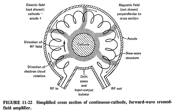
The cross section of a typical Crossed Field Amplifier is shown in Figure 11-22; the similarity to a coaxial magnetron is striking in its appearance. It would have been even more striking if, as used in practice, a vane slow-wave structure had been shown, with waveguide connections. The helix is illustrated here purely to simplify the explanation. Practical CFAs and magnetrons are very difficult to tell apart by mere looks, except for one unmistakable giveaway: unlike magnetrons, CFAs have RF input connections.
As in the magnetron, the interaction of the various fields results in the formation of bunched electron clouds. An input signal is supplied and receives energy from electron clouds traveling in the same direction as the RF field. In the TWT, signal strength grows along the slow-wave structure, and gain results. It will be seen in Figure 11-22 that there is an area free of the slow-wave structure. This provides a space in which electrons drift freely, isolating the input from the output to prevent feedback and hence oscillations. An attenuator is sometimes used also, similar to the TWT arrangement.
In the tube shown, the direction of the RF field and the electron bunches is the same; this is a forward-wave Crossed Field Amplifier. Backward-wave CFAs also exist, in which the two directions are opposed. There are also CFAs which have a grid located near the cathode in the drift-space area, with an accelerating anode nearby. They are known as injected-beam CFAs.
Practical considerations:
The majority of Crossed Field Amplifier are pulsed devices. CW and dual-mode CFAs are also available, although their performance and other details tend to be shrouded in military secrecy. However, dual-mode operation is easier for CFAs than for TWTs, because here both the electric and the magnetic fields can be switched to alter power output. Thus 10:1 or higher power ratios for dual-mode operations are feasible.
Pulsed CFAs are available for the frequency range from 1 to 50 GHz, but the upper frequency is a limit of existing requirements rather than tube design. CFAs are quite small for the power they produce (like magnetrons), and that is a significant advantage for airborne radars. The maximum powers available are well over 10 MW in the UHF range (with an excellent efficiency of up to 70 percent), 1 MW at 10 GHz (efficiency up to 55 percent) and 400 kW CW in the S-band. The excellent efficiency contributes to the small relative size of this device and of course to its use. Duty cycles are up to about 5 percent, better than magnetrons but not as high as TWTs. Bandwidths are quite good at up to 25 percent of center frequency (and one octave for some injected-beam CFAs). The relatively low gains available, typically 10 to 20 dB, are a disadvantage, in that the small size of the tube is offset by the size of the driver, which the klystron or TWT, with their much higher gains, would not have required.
A typical forward-wave Crossed Field Amplifier is the Varian SFD257. It operates over the range 5.4 to 5.9 GHz, producing a peak power of I MW with a duty cycle of 0.1 percent. The efficiency is 50 percent, gain 13 dB, and noise figure approximately 36 dB, a little higher than for a corresponding klystron. The anode voltage is 30 kV dc, and the peak anode current is 70 A. The tube, like a number of magnetrons, uses back-heating for the cathode, and indeed both it and the anode are liquid-cooled. The whole package, with magnet, weighs 95 kg and looks just like a high-power magnetron with an extra set of RF terminals. Crossed Field Amplifier are used almost entirely for radar and electronic countermeasures.
Backward Wave Oscillator:
A backward wave oscillator (BWO) is a microwave CW oscillator with an enormous tuning and overall frequency coverage range. It operates on TWT principles of electron beam-RF field interaction, generally using a helix slow-wave structure. In general appearance the BWO looks like a shorter, thicker TWT.
Operation:
If the presence of starting oscillations may be assumed, the operation of the BWO becomes very similar to that of the TWT. Electrons are ejected from the electron-gun cathode, focused by an axial magnetic field and collected at the far end of the glass tube. They have meanwhile traveled through a helix slow-wave structure, and bunching has taken place, with bunches increasing in completeness from the cathode to the collector. An interchange of energy occurs, exactly as in the TWT, with RF along the helix growing as signal progresses toward the collector end of the helix. Unlike the TWT, the BWO does not have an attenuator along the tube. As a simplification, oscillations may be thought of as occurring simply because of reflections from an imperfectly terminated collector end of the helix. There is feedback, and the output is collected from the cathode end of the helix, toward which reflection took place. Because the helix is essentially a nonresonant structure, bandwidth (if one may use such a term with an oscillator) is very high, and the operating frequency is determined by the collector voltage together with the associated cavity system.
Bandwidth is limited by the interaction between the beam and the slow-wave structure. To increase this interaction, the BWO has a ring cathode which sends out a hollow beam, with maximum intensity near the helix.
Practical aspects:
Backward-wave oscillators are used as signal sources in instruments and transmitters. They can also be made broadband noise sources, whose output, amplified by an equally wideband TWT, is transmitted as a means of enemy radar confusion. The frequency spectrum over which BWOs can be made to operate is vast, stretching from 1 to well over 1000 GHz. The Thomson-CSF CO 08 provides about 50 mW CW over the range 320 to 400 GHz, while 0.8 mW CW has been reported, from another BWO, at 2000 GHz. The normal output range of BWOs is 10 to 100 mW CW, but tubes with outputs over 20 W, at quite high frequencies, have also been produced. The tuning range of a BWO is an octave typically, up to about 40 GHz. At higher frequencies multiple helixes or coupled cavities are used, with a consequent bandwidth reduction to typically a half-octave. At the lower end of the spectrum, frequency ranges over 3:1 are possible from the one tube. The ITT F-2513 produces an average of 25 mW over the range 1.3 to 4.0 GHz. The rate at which the BWO frequency may be changed is very high, being measured in gigahertz per microsecond.
Permanent magnets are normally used for focusing, since this results in simplest magnets and smallest tubes. Solenoids are used at the highest frequencies, since it has been found that they give the best penetration and distribution for the axial magnetic field. A recent development in this respect has been the use of samarium-cobalt permanent magnets to reduce weight and size.
The Siemens RWO 170 is a typical BWO and produces an average power output of 10 mW. It is electronically tunable over the range from 60 GHz (at which the collector voltage is 500 V) to 110 GHz (collector voltage 2500 V). The average collector current is 12 to 15 mA and dissipation about 30 W. Together with its power supply and magnet, it weighs 2 kg.