Conventional DC and AC Traction Drives:
The commonly used Conventional DC and AC Traction Drives are
The dc Traction Drives Employing Resistance Control:
The dc traction drives employing resistance control are:
- 1500 V dc traction on Bombay-Igatpuri-Pune section for main line and Bombay suburban
- 750 V dc traction in underground trains at Calcutta.
- 550 V dc traction in Calcutta tramways.
Each motor coach of 1500 and 750 V dc tractions have four dc series motors with voltage ratings of 750 and 375 V, respectively; two motor are permanently connected in series. Similar connection is used in locomotives for 1500 V main line dc traction. The 550 V dc traction of Calcutta tramways use two dc series motors each rated 550 V.
Basic control scheme for all these drives is essentially the same. When four motors are used, two motors are permanently connected in series to form one pair. Thus, the drive will have two pairs each having two motors permanently connected in series. Starting, speed control and torque control up to base speed is carried out with the help of contactor-controlled sectionalised resistors. At start both motor-pairs are connected in series with the sectionalised resistors in series as shown in Fig. 10.10(a). As the train accelerates resistor-sections are cut out one by one so as to limit the starting current within prescribed maximum and minimum limits. When all sections of resistance controller are cut out, the motor speed will be nearly half of base speed.
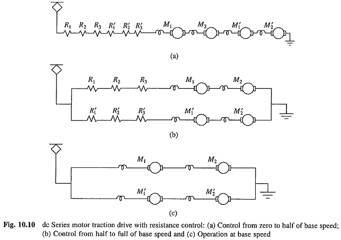
For further acceleration, the two motor pairs are connected in parallel with the sectionalised resistor in series with each of them (Fig. 10.10(b)). The resistor-sections are now cut out, one by one to limit the current within prescribed maximum and minimum limits. When all resistor-sections are cut out (Fig. 10.10(c)), motors will be running around the base speed. Speeds higher than base speeds are obtained by field control. For changing the field current, diverter resistors are connected in parallel with field windings. Different steps of control for a motor coach with two motors is obtained when each pair in Fig. 10.10 is replaced by one motor.
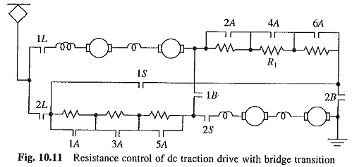
During transition from series to parallel connection closed circuit transition has to be applied, because it is not desirable to break such a high current. Further, the sudden change of current at the time of opening and reconnection will produce step change in torque, causing discomfort to passengers and increasing tendency for wheel slip. To avoid this, closed circuit transition is used. Figure. 10.11 shows the closed circuit transition using what is known as bridge circuit transition.
Different steps of control are:
(i) close 1L, 1S and 2S, which connects both motor pairs 1 and 2 in series with sectionalised resistors R1 and R2;
(ii) close progressively 1A to 6A, now motor speeds are nearly half of base speed;
(iii) close 1B;
(iv) open 1S and 1A to 6A;
(v) close 2L and 2B;
(vi) open 1B, this connects two motor pairs with a sectionalised resistance in series with each, in parallel; without opening motors armature and field circuits
(vi) close contacts 1A-2A, 3A-4A and 5A-6A in pairs successively. This connects two motor pairs in parallel and starting process is completed.
For dynamic braking, supply is switched off, fields are reversed and sectionalised resistors are connected across each motor pair. The motors work as self-excited generator. As the train decelerates, resistor’s sections are cut out one by one to maintain good braking torque. As the braking ceases at a finite speed, mechanical brakes are applied to stop the train. During dynamic braking, larger resistance is required than during starting. Therefore, additional sectionalised resistor is employed along with starting resistor.
Dynamic braking is not always used. For example in India while underground trains in Calcutta use dynamic braking but not the trains of 1500 V dc traction in Bombay. The torque control during motoring and braking is realised by changing the value of armature circuit resistance.
Additional features are incorporated for smooth acceleration of the train. The first few steps during starting are chosen such that the current, and therefore, torque is build up in small steps to avoid any jerk. These steps may be implemented based on the values of dl/dt, whereas later steps are based on the value of I.
As a number of operations are involved, it will be very tiring for the driver to carry them out manually. Automatic controls using contactors and servo drives are used to simplify the job of the driver.
The above dc traction schemes have several disadvantages.
- Low efficiency due to resistance control.
- Poor adhesion due to: (a) step change in torque and (b) more drooping speed-torque curves because of resistance control.
- Frequent maintenance due to large number of moving contacts.
- Unless very large sections are used in the starting and braking resistances, average accelerating and decelerating torques are substantially lower compared to the maximum torque the motors can produce. This slows down the average speed of a suburban train.
The 25 kV, 50 Hz ac Traction Using On-Load Transformer Tap Changer:
This scheme has been used both for main line and suburban trains. In India it is widely used for main line traction. All main line electric traction schemes, except Bombay-Igatpuri-Pune route, are using this scheme. The drive scheme is shown in Fig. 10.12.
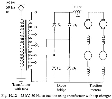
A step down transformer reduces the voltage from 25 kV to a suitable value. The secondary winding is provided with tappings. An on-load tap changer (Fig. 5.24) is used to vary the taps on transformer without voltage surges. A diode rectifier bridge converts ac to dc and through somoothing reactor Ld feeds dc series traction motors, which are connected in appropriate series- parallel combinations. Usually a locomotive with four motors will have series-parallel connection as shown in Fig. 10.12.
As explained earlier, the tendency for wheel slip will be lowest when all motors are connected in parallel, but then the transformer secondary current rating will be the highest. On the other hand, the transformer current rating will be the lowest and the tendency for wheel slip will be highest when all four motors are connected in series. The connection of Fig. 10.12 provides a compromise between the two contradictory requirements. The smoothing reactor Ld may be divided into four sections, one in series with each traction motor, so that in the event of a motor fault, a high impedance is in the circuit and motor protection is simplified. For starting, and speed and torque control up to base speed, the motor terminal voltage is varied by changing taps on the transformer. The speed control above base speed is obtained by connecting a diverter resistor in parallel with the field of each motor. Braking is generally provided by mechanical brakes. Dynamic braking has also been used. For this, motors have been connected as separately excited generators. Fixed braking resistors are connected across armatures of each motor. The fields of all motors are connected in series across an auxiliary dc generator driven by an auxiliary induction motor. The current through the motor fields is controlled by controlling the field current of the auxiliary dc generator. As the motor decelerates under braking, the motor field current is increased to maintain a specified current through the motor armature.
The tap-changer may have 20 to 40 taps. Varying them manually can be very tiring for the driver. Therefore, tap changer control has to be automatic. Contactors and servo drives are used to realise automatic control of the tap-changer.
The following advantages over dc drives employing resistance control:
- Higher efficiency as the starting, speed and torque control are done by varying armature voltage instead of armature resistance.
- Better adhesion, because with armature voltage control the motor speed-torque characteristics are less drooping compared to armature resistance control.
- In underground trains, one is forced to use low voltage due to limited space available between the train and tunnel. No such restriction is applicable to over ground traction. In case of dc traction, the maximum transmission voltage depends on the number of motors in series and their voltage rating because no simple means were available for stepping down the dc voltage. As the dc motor voltage rating because of commutator is restricted to 750 V dc and since two motors are permanently connected in series, the dc transmission voltage is chosen as 1500 V. In ac transmission as the voltage can be stepped down easily and efficiently by a transformer, it is possible to use 25 kV voltage for transmission. Because of the much higher transmission voltage, the cost of transmission and power loss in transmission are much lower in 25 kV ac traction than in 1500 V dc traction. Because of high cost, 1500 V dc traction is not used in new installation. Although because of the prohibitive cost of replacement it continues to be there wherever it was installed prior to the development of 25 kV ac traction.
The 25 kV ac traction using transformer with tap changer has following limitations:
- Due to a larger number of moving contacts and parts, the tap changer requires frequent maintenance and is susceptible to frequent failures and fire hazards.
- As the motor voltage is controlled in steps, adhesion is poor and maximum accelerating torque is lower compared to what can be achieved with stepless control using semiconductor converters.