Control of DC Drives Using Microprocessors:
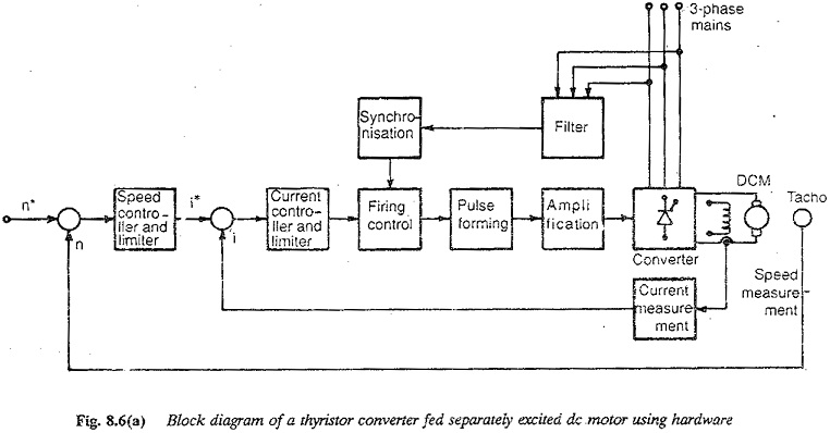
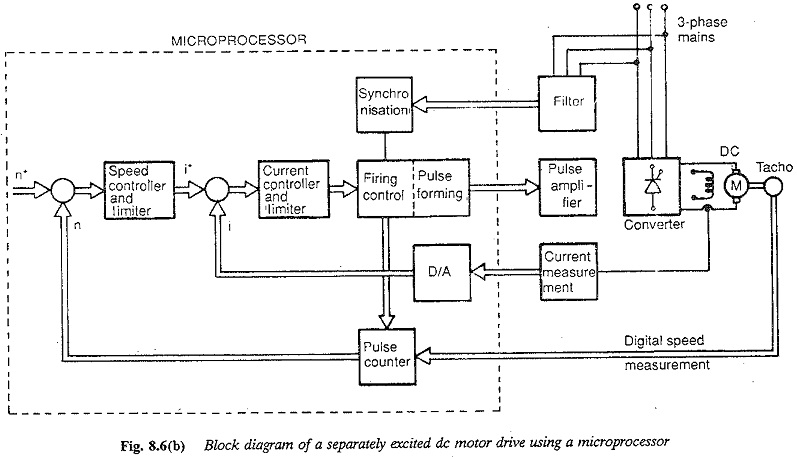
The dc motors fed from thyristor converters for variable speeds are being extensively used in general industrial applications. A dual converter, which is a combination of two antiparallel connected three phase/single phase bridge converters, provides a reversible Control of DC Drives Using Microprocessors with regenerative facilities. The response of the drive is fast. The speed control systems of the drive using the dedicated hardware with discrete components as well as a microprocessor, are shown in Fig. 8.6. Figure 8.6 clearly specifies the functions of a microprocessor in such a system. The scheme requires a number of parts or components and careful adjustment when based on analog techniques. However, by proper selection of counters to perform several jobs, the number of components can be reduced. The microprocessors effectively replace these schemes for dc motors of high performance because of their varied functional capabilities. At the outset it may seem that the interface circuits between the microprocessor and the system tend to increase the overall cost and decrease the advantage of Control of DC Drives Using Microprocessors. However the improvement in the functions, reliability, size of the control equipment, and rapid reduction in manufacturing costs are possible with the fast growth and developments of digital systems and A/D and D/A converters, to make the system economical and cost effective. Among the functional capabilities of a Control of DC Drives Using Microprocessors are higher level reliability, availability, and serviceability, which are instrumental in the increase of productivity of a drive.
The following are the functions of a microprocessor in the control of a dc motor fed from a dual converter:
Speed sensing: As has already been explained, a digital speed encoder provides the information concerning the speed to a microprocessor. The train of pulses from the shaft encoder are processed in the microprocessor to estimate the speed.
Feedback control: The closed loop control here has an inner current loop and an outer speed loop. The necessary reference values are stored in the memory of the microprocessor. The current is measured and converted to a digital quantity using an A/D converter. After conversion the signal is fed to the microprocessor based control system. The speed signal is available in digital form. The necessary controllers and limiters can be implemented on the microprocessor, as has already been explained. The controllers implemented on a microprocessor are adaptive. These improve the performance and flexibility of the Control of DC Drives Using Microprocessors. The system must be capable of taking care of variable gain during field weakening mode as decided by the operating condition to obtain the desired speed-torque characteristic.
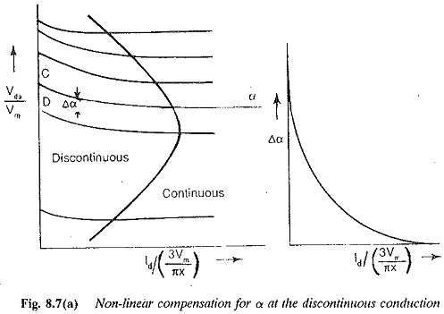
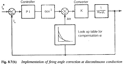
A converter feeding a back emf load (as in the control of dc motor) operates in the discontinuous mode of operation under certain conditions of loading. The converter possesses a non-linear transfer characteristic with variable gain. The performance of the drive is sluggish. The non-linearity must be compensated by a proper feedback loop or linearising the operation using an inverse non-linear function. This function of the Control of DC Drives Using Microprocessors must be supported by a suitable software. When the conduction is continuous the converter voltage is a constant, independent of load. In the discontinuous conduction, the angle of conduction and hence the converter voltage depend on the load. When once the discontinuous current limit is reached at a firing angle (Fig. 8.7), the converter voltage increases. To bring the value of Vd to the value corresponding to continuous conduction the firing angle must be increased by Δα. From the external characteristic of the converter the change in Δα as a function of Id at a given firing angle a can be stored in a look-up table. The firing of the converter is controlled so that the gain of the converter is invariant. The non-linear characteristic of Δα vs Id at a given firing angle is shown in Fig. 8.7, and the block diagram implementing the correction is shown in Fig. 8.7(b).
The digitized ac power signals are used to determine the firing delay with respect to the natural firing instant. The firing scheme must provide high dynamic performance to the drive, besides reducing the number of components.
The dual converter has two modes of operation. They are non-circulating current mode and circulating current mode. In the former only one converter is conducting whereas the other is in a non-conducting state. In the latter both the converters operate simultaneously with suitable firing angles. The firing pulse generation and the control logic depend upon the mode of operation. In the non-circulating current mode of operation the transition from one converter to the other takes place when the current passes through zero. The zero current persists for a short interval so that the outgoing (thyristor) converter is completely blocked before the pulses are given to the incoming one. In the circulating current mode, however, the current is continuous and transition problems are not there, as both the converters conduct simultaneously. The circulating current mode of operation is employed when zero current intervals cannot be tolerated. There are structural differences in the power circuits of these modes of operation. Similarly, software development for generation of the firing pulses must consider these aspects carefully. In the non-circulating current mode of operation zero detection of the current is required during the transition from one converter to the other. Also, there may be discontinuous conduction in this mode of operation. The program must be able to distinguish between the actual zero crossing and the discontinuous conduction. The firing circuit for non-circulating current mode is rather involved because of the features described above, whereas the circuit for circulating mode is simpler.
The digital firing angle controller should be programmable, should generate accurate gate pulses in various configurations discussed above, and should perform gating at accurately repeated intervals with the desired symmetry and independent of frequency. If must also be possible to alter the firing angle on line, without disturbing the symmetry of pulse train.
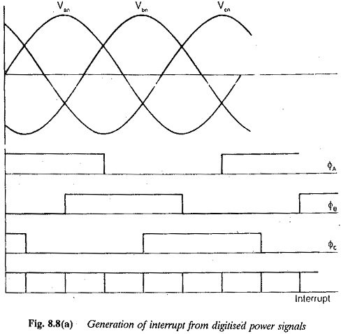
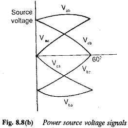
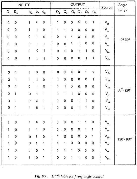
The interface between the supply line and microprocessor is required to provide the necessary synchronisation of the firing pulses with the ac voltages. This converts analog ac signals to digital signals for feeding to the microprocessor. The converter receives the firing pulses in intervals of 60° as per the firing sequence. The Control of DC Drives Using Microprocessors may be made to perform the function of generating firing pulses by means of an interrupt signal. This signal has a frequency double that of the line. The interrupt signal occurs at 0°, 60°, 120°, 180°, 240° and 300°. A new firing sequence may be started at the falling edge of the interrupt. The hardware implementation and the signals are shown in Fig. 8.8. A Control of DC Drives Using Microprocessors the processes of a general servo system may be used to generate the firing pulse by going through the pulse generation program by means of the interrupt signal. After successfully completing the job the microprocessor will return to the normal function. The program should take care of performing the firing range selection, protection, etc. The firing angle range can be detected using the information of the line voltages of 1/6 cycle. This information must be sufficient to cover 0 to 180° in both the be demultiplexed and amplified before they are fed to the thyristors. By this a saving of the hardware of the processor and I/O may be accomplished, which can be used effectively for other purposes. The necessary hardware and truth table for generating firing pulses are shown in Fig. 8.9. The gate firing program must handle both continuous and discontinuous conductions if the converter operates in the non-circulating mode of operation. The appropriate converter must be fired depending upon the current direction. The discontinuous conduction must not be confused with zero of the current during transition, in order to assure the reliable firing of the converter.
The necessary logic must be designed considering the following:
- When the load current is positive converter A conducts and when it is negative the converter B conducts.
- If there is no discontinuous conduction sensing of either load current or thyristor conduction may be used.
- Zero current does not mean that transition should occur.
- When the load current is fetched to assess the condition of zero current it does not always mean that the transition should occur.
- Gain compensation during discontinuous conduction or field weakening mode.
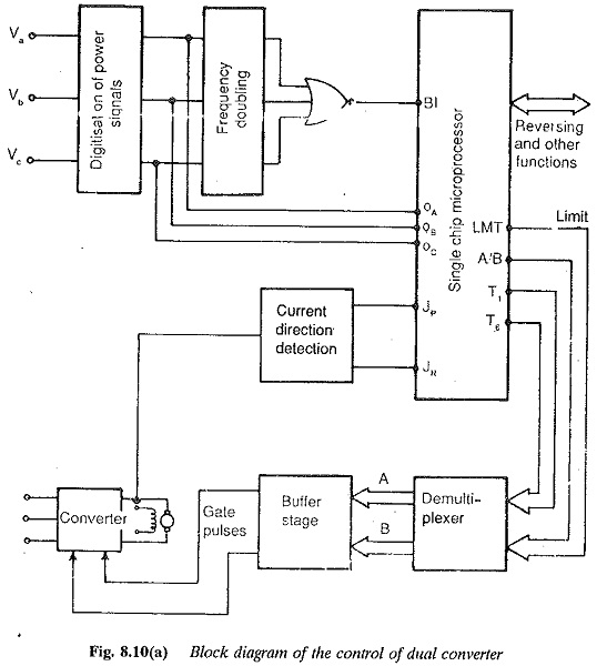
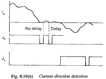
The current direction can be sensed by the so-called current direction signals. These signals are delayed by a definite time period, normally greater than the turn off time of the thyristors, to make sure that the thyristor has turned off. The simultaneous zero values of the signals indicate that no thyristor is conducting. If one of the signals is zero, the converter with non-zero signal is conducting. The other converter cannot get firing pulse so that a short circuit is avoided. This logic is depicted in. Fig. 8.10. The line voltages of 1/6th cycle provide the information of the direction of current in a given range of firing angle.
To summarise, in a non-circulating current mode of operation the following points need consideration while developing software.
- When the thyristors in one converter are conducting at any instant of time the other converter cannot be fired. During transition from one converter to the other it must be ensured that the outgoing converter is completely blocked before the incoming one is fired.
- When once the zero crossing of the armature current is sensed, a definite delay must be provided to ensure that the thyristors have regained their positive blocking capability.
- To arrive at proper logic, the state of load current is checked but not that of an SCR.
In some applications, such as servo drives, the delay cannot be tolerated during transition, however small it may be. The circulating current mode is employed. A reactor is used to limit the circulating current. The firing logic is very simple here, as there is no zero current to be detected and no discontinuous conduction at all.
The Control of DC Drives Using Microprocessors must also provide suitable protections against failure of any of the phases, commutation failure, cross over condition, etc. The system reliability increases with multilevel protection.
Selection of a Control of DC Drives Using Microprocessors
From the above discussion the criteria for the selection of microprocessor for the control of a dual converter may be derived:
- The main function of the microprocessor is generating the firing pulses with least possible asymmetry, The asymmetry level is decided by the resolution of the firing angle. To get a resolution of the order of 1°-2° the sampling processor chosen must be capable of small cycle and computing time to allow for high rates of sampling control.
- The accuracy in the calculation of current and speed loops. The sampling periods of these loops are however larger than those of the generating pulses. The error in computation must be limited.
- If extra accuracy is required in the speed loop the microprocessor must be capable of floating point arithmetic in order to handle large numbers. For this purpose a fast microprocessor with optimised programs may be required.
Some other applications of microprocessors in the area of dc drives are
- chopper controlled four quadrant dc drives using separately excited dc motor or dc series motor.
- multiphase chopper controlled dc drives
- pulse width controlled dc drives
- The multiple firing schemes for improving the performance of dc drives, g., TRC and CLC.