Comparison Bridge:
There are two types of Comparison Bridge, Namely
- Capacitance Comparison Bridge
- Inductance Comparison Bridge
1. Capacitance Comparison Bridge:
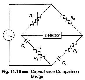
Figure 11.18 shows the circuit of a capacitance comparison bridge. The ratio arms R1, R2 are resistive. The known standard capacitor C3 is in series with R3. R3 may also include an added variable resistance needed to balance the bridge. Cx is the unknown capacitor and Rx is the small leakage resistance of the capacitor. In this case an unknown capacitor is compared with a standard capacitor and the value of the former, along with its leakage resistance, is obtained. Hence.

The condition for balance of the bridge is
![]()
i.e.
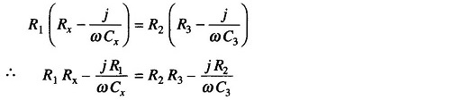
Two complex quantities are equal when both their real and their imaginary terms are equal. Therefore,
i.e.
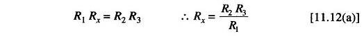
and
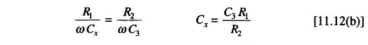
Since R3 does not appear in the expression for Cx, as a variable element it is an obvious choice to eliminate any interaction between the two balance controls.
2. Inductance Comparison Bridge:
Figure 11.20 gives a schematic diagram of an inductance comparison bridges. In this, values of the unknown inductance Lx and its internal resistance Rx are obtained by comparison with the standard inductor and resistance, i.e. L3 and R3.
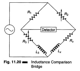
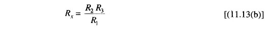
The equation for balance condition is
![]()
The inductive balance equation yields
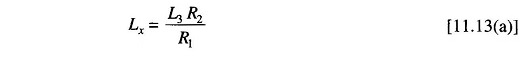
and resistive balance equations yields
In this bridge R2 is chosen as the inductive balance control and R3 as the resistance balance control. (It is advisable to use a fixed resistance ratio and variable standards). Balance is obtained by alternately varying L3 or R3. If the Q of the unknown reactance is greater than the standard Q, it is necessary to place a variable resistance in series with the unknown reactance to obtain balance.
If the unknown inductance has a high Q, it is permissible to vary the resistance ratio when a variable standard inductor is not available.