Colpitts Oscillator using Op Amp:
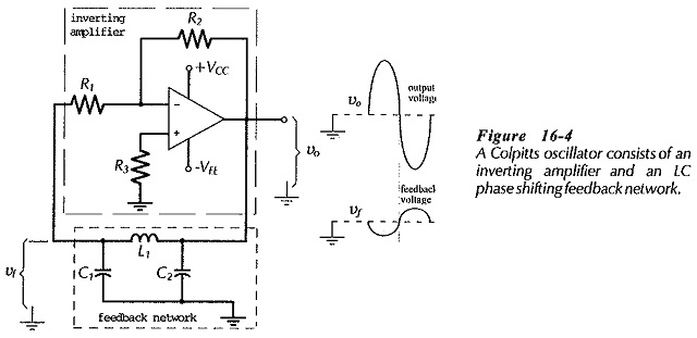
The Colpitts Oscillator using Op Amp circuit show in Fig. 16-4 is similar to the op-amp phase shift oscillator, except that an LC network is used to produce the necessary phase shift in the feedback voltage. In this case, the LC network acts as a filter that passes the oscillating frequency and blocks all other frequencies. The filter circuit resonates at the required oscillating frequency.
For resonance,![]()
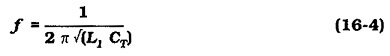
where XCT is the total capacitance in parallel with the inductor. This gives the resonance frequency (and oscillating frequency) as,
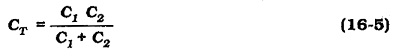
Capacitors C1 and C2 are connected in series across L1; so,
Consideration of the LC network shows that its attenuation (from the amplifier output to input) is due to the voltage divider effect of L and C1. This gives,
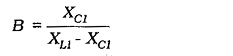
It can be shown that the required 180° phase shift occurs when
![]()
and this gives,
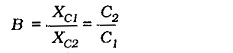
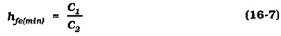
As in the case of all oscillator circuits, the loop gain must be a minimum of one to ensure oscillation. Therefore,
![]()
or,
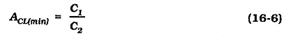
When deriving the above equations, it was assumed that the inductor coil resistance is very much smaller than the inductor impedance; that is, that the coil Q factor (ω L/R) is large. This must be taken into considered when selecting an inductor. It was also assumed that the amplifier input resistance is much greater than the impedance of C1 at the oscillating frequency. Because of the inductor resistance and the amplifier input resistance, and because of stray capacitance effects when the oscillator operates at a high-frequency, the amplifier voltage gain usually has to be substantially larger than C1/C2.
Circuit Design:
Colpitts oscillator design can commence with selection of the smallest capacitor (C2) much larger than stray capacitance, or with selection of a convenient value of L. To keep the amplifier input voltage to a fairly low level, the feedback network is often designed to attenuate the output voltage by a factor of 10. This requires that C1/C2 ≈ 10. (It should be recalled that large ACL values require larger op-amp bandwidths.) Also, XC2 should be much larger than the amplifier output impedance. Using the desired oscillating frequency, L can be calculated from Eq. 16-4. Amplifier input resistor R1 must be large enough to avoid overloading the feedback network, (R1 ≫ XC1). Resistor R2 is determined from ACL and R1.
BJT Colpitts Oscillator:
A Colpitts oscillator using a single BJT amplifier is shown in Fig. 16-6(a). This is the basic circuit, and its similarity to the op-amp Colpitts oscillator is fairly obvious. A more complex version of the circuit is shown in Fig. 16-6(b).
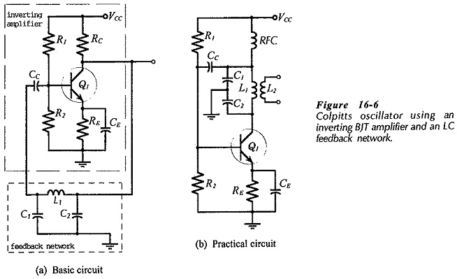
Components Q1, R1, R2, RE and CE in (b) are unchanged from (a), but collector resistor RC is replaced with inductor L1. A radio frequency choke (RFC) is included in series with VCC and L1. This allows dc collector current (IC) to pass, but offers a very high impedance at the oscillating frequency, so that the top of L1 is ac isolated from VCC and ground. The output of the LC network (L1, C1, C2) is coupled to via Cc to the amplifier input. The circuit output voltage (vo) is derived from a secondary winding (L2) coupled to L1. As in the case of the BJT phase shift oscillator, the transistor current gain is important. Circuit analysis gives Eq. 16-4 for frequency, and for current gain,