Coaxial Cable in Communication System:
A Coaxial Cable in Communication System consists of a tube carrying a number of coaxial cables of the type, together with repeaters and other ancillary equipment. Separate cables are used for the two directions of transmission, and a pair of spare cables is also provided for protection in case of failure. The number of Coaxial Cable in Communication System per tube may be as low as four in smaller systems or as high as 22 in major systems, as illustrated, in Figure 15-4. The typical number of channels per cable varies from 600 in a 3-MHz system to 3600 in an 18-MHz system.
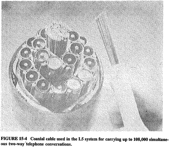
Since signals are attenuated as they travel along the Coaxial Cable in Communication System, amplifying repeaters must be placed at suitable intervals along the route. The distance varies, being roughly inversely proportional to the bandwidth of the system. It may be as much as 10 km between repeaters for a small system, but in the L5 system of Figure 15-4, where bandwidths for all cables are nearly 58 MHz, repeaters are placed at 1.6-km intervals. Since there are repeaters, a dc supply must be fed to the cable to power them. In the L5 system, dc power-feeding stations are located 120 km apart, i.e., 75 repeaters apart.
Assuming an 18-V drop across each repeater, and noting that repeaters are in series for direct current since otherwise the required currents would be too high, this means that the dc voltage applied at each station must be 1350 V. To minimize insulation problems, what is done in practice is to apply voltages of half that value, but of opposite polarities, at the two adjoining dc feed stations. A station at one end may thus feed +675 V to the cable, while the next station along feeds -675 V toward the first station and +675 V toward the next station down the cable.
Broadband systems must have excellent frequency and phase-delay responses to be of use. This cannot be achieved by cables and repeaters unaided, so that equalizers are also located along the cable, 60 km apart in the L5 system. It should be noted that there is need for two kinds of equalizers. The fixed type compensates for constant, known deviations in frequency and phase response which are inherent in each particular system. Adjustable equalizers, generally provided at the two ends of the system, are used to compensate for the variables and the unpredictable variations. Where adjustable equalizers are located in underground stations along the cable, they are normally adjustable in steps rather than continuously.
In modern systems these adjustments may be made from the control stations at the ends, by sending appropriate signals down the Coaxial Cable in Communication System. Finally, to ensure constant gain along the system, thus preventing excessive noise and inter-modulation distortion, the gain of repeaters is regulated. This may be done by having adjustable-gain repeaters at intervals along the cable and altering their gain as required with suitable control signals.
Multiplexing and demultiplexing bays form the major portion of the terminal equipment. Dc power feed equipment is also located at the terminals, as are interconnections to other systems, be they local or trunk. Surveillance equipment is also provided at terminal stations. It is here that system pilots are applied, and those that were applied at the other end are extracted. A distinction should be made between a supergroup or even supermastergroup pilot and a system pilot. The latter belongs to the system and is used for end-to-end system regulation and monitoring. The supergroup pilot is applied at the point at which the supergroup is formed and extracted at the point at which it is broken up. It is used for regulating and monitoring that particular supergroup, which may traverse many different links.
Although each is regulated, small, in-tolerance departures from correct response in the various links may be additive, resulting in a supergroup that is out of tolerance end to end. Finally, each terminal is provided with equipment which, should there be a cable failure, permits it to interrogate the repeaters in the link, so as to allow quick localization of the fault. Furthermore, to minimize the effects of outages, terminal stations may be provided with redundant and/or duplicated systems, allowing their staff to patch rapidly around any breaks.
Some students may wonder why communications systems tend to have more and more capacity. The answer is that long-distance telephony, telex and television transmissions in most countries have been increasing at high rates, for over two decades, while data transmission in developed countries is growing at very high annual rates of close to 50 percent. Coupled to this demand growth is the fact that a 10,800-channel system is decidedly cheaper M install and maintain than three 3600-channel systems. Such broadband links are manufactured by some of the world’s most modern, efficient and reliable companies.