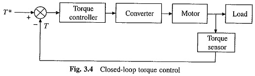
Closed Loop Torque Control of Drives:
Closed Loop Torque Control of Drives scheme of Fig. 3.4 finds application in battery operated vehicles, rail cars and electric trains. Driver presses the accelerator to set torque reference T*. Through Closed Loop Torque Control of Drives, the actual motor torque T follows torque reference T*. Speed feedback loop is present through the driver. By putting appropriate pressure on the accelerator, driver adjusts the speed depending on traffic, road condition, his liking, car condition and speed limit.
Closed Loop Speed Control:
Figure 3.5 shows a closed loop speed control scheme which is widely used in electrical drives. It employs an inner current control loop within an outer speed-loop. Inner current control loop is provided to limit the converter and motor current or motor torque below a safe limit. In some schemes the current is controlled directly. In others it may be controlled indirectly. For example, in a variable frequency induction motor drives the current is controlled by controlling the slip.
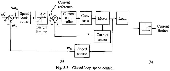
Inner current loop is also beneficial in reducing the effect on drive performance of any non-linearity present in converter-motor system. Drive of Fig. 3.5 operates as follows:
An increase in reference speed ω*m produce a positive error Δωm. Speed error is processed through a speed controller and applied to a current limiter which saturates even for a small speed error. Consequently, limiter sets current reference for inner current control loop at a value corresponding to the maximum allowable current. Drive accelerates at the maximum allowable current (and in some cases at the maximum torque). When close to the desired speed, limiter desaturates. Steady-state is reached at the desired speed (with some steady-state error) and at current for which motor torque is equal to the load torque.
A decrease in reference speed ω*m produces a negative speed error. Current limiter saturates and sets current reference for inner current loop at a value corresponding to the maximum allowable current. Consequently, drive decelerates in braking mode at the maximum allowable current. When close to the required speed, current limiter desaturates. The operation is transferred from braking to motoring. Drive then settles at a desired speed and at current for which motor torque equals the load torque. In those drives where the current I does not have to reverse for braking operation, current limiter will have the input-output characteristic shown in Fig. 3.5(b). In those drive applications where the load torque is able to provide enough decelerating torque, electric braking need not be used. Then also current limiter has the characteristic shown in Fig. 3.5 (b).
Current and speed controllers shown in Figs. 3.4 and 3.5 may consists of proportional and integral (PI), proportional and derivative (PD) or proportional, integral and derivative (PID) controller, depending on steady-state accuracy and transient response requirements.