Closed Loop Speed Control of Multi Motor Drives:
When mechanical part of the load is of large physical dimension it becomes desirable to share the load between several motors. For example a rotary printing press usually has several printing stations which are mechanically coupled by a long drive shaft. Each section (printing station) is driven by its own motor, which carries most of its load. As load requirements may be different, the motor ratings may also be different for each section, although all of them must run at the same speed. Once it is ensured that torque requirement of each section is met by its own driving motor, the drive shaft has to carry only small synchronizing torque. Sections (n — 1) and n of such a multi-motor drive arc shown in Fig. 3.6(b). Section n is coupled to Section (n — 1) by clutch Cn-1, and so on. A suitable Closed Loop Speed Control of Multi Motor Drives scheme is shown in Fig. 3.6(a). It consists of one common outer speed-loop and one inner torque control loop for each section. As all sections run at same speed, one speed control loop is enough: Speed feedback may be obtained from a suitably placed speed sensor. The common speed controller, through gain constants K1,K2, . . .Kn, sets reference torques for the closed-loop torque control of sections 1, 2, . . . , n respectively; thus ensuring that the torques are shared in proportion to motor ratings.
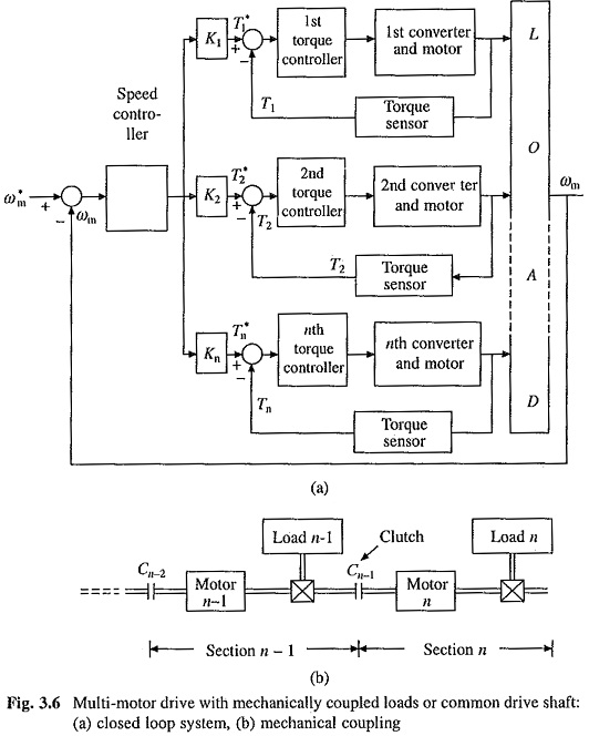
Such multi-motor drives are also employed in electric and diesel electric locomotives, rapid transit vehicles and some paper machines. In a locomotive because of different amount of wear and tear, all wheels do not have the same diameter. Therefore, for a given speed of train they would revolve at different speeds. Consequently, the driving motor speeds will also be different. In spite of different speeds it is essential that torques are shared equally between different motors; otherwise when one motor is fully loaded others will be under loaded, and thus, the rated locomotive torque will be less than the sum of individual motor torque ratings. Here also a single outer speed loop, with speed feedback derived from a suitably located speed sensor, is enough. Because each motor has its own torque control loop, in spite of their different rotational speeds, they are made to share the torque equally.
In multi-motor drives discussed above various sections of drive are mechanically coupled through a long shaft. In other class of multi-motor drives, which are employed in continuous production processes, various sections are not coupled through a long shaft. However, they get coupled through the material under process as it simultaneously passes through the sections.
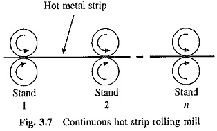
Continuous hot strip rolling mills, fibre spinning mills and paper mills without mechanical drive shafts are examples of such multi-motor drives. Figure 3.7 depicts an n stand continuous hot strip rolling mill. Red hot strip simultaneously passes through all rolling stands. Rollers of each stand, are driven by its own individual motor. Various stands which are not mechanically coupled through a long shaft get coupled through a thin red hot strip which cannot sustain any appreciable forces; on the other hand, strip must be kept sufficiently tight in order to avoid folds and crease.
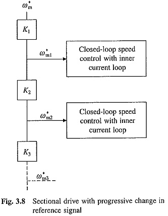
As the material passes through a rolling stand, its cross section decreases, and therefore, its length and velocity increase. In order to keep the strip tension within suitable limits, the motor of next rolling stand must run at an appropriate higher speed. This can be implemented by the Closed Loop Speed Control of Multi Motor Drives schemes of Figs. 3.8 and 3.9. In both the schemes, each rolling stand has its own Closed Loop Speed Control of Multi Motor Drives scheme with an inner current control loop. However, the speed references are derived in different ways. Scheme of Fig. 3.8 employs a cascade structure, also known as progressive draw, to generate speed reference signals. In this scheme ratio of successive reference speeds remains fixed, i.e.
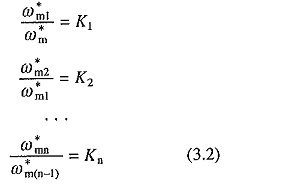
where K1, K2, . . , Ku are constants. For any r th rolling stand
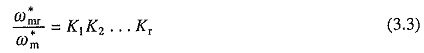
As the command reference speed ω*m is changed, all other reference speeds ω*m1 . . . ω*mn will also change in proportion to ratios given by Eqs. (3.2). With ω*m held constant, if the speed ratio of any successive stage is altered, it will affect the reference speeds of all succeeding stages but not of preceding stages.
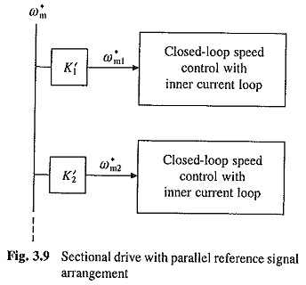
In scheme of Fig. 3.9, reference speeds are generated in parallel and are given by
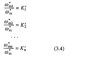
where K′1, K′2, . . . , K′n are constants. Here reference speed of any section can be changed independent of other sections by changing the gain constant associated with it.