Closed Loop Control of DC Motor:
Closed Loop Control of DC Motor – The dynamic behaviour of a system is described by a set of differential equations. On many occasions the solution of these equations requires the evaluation of convolution integrals which may be a difficult task. In such cases a simpler analysis is made feasible by the use of transfer functions making use of Laplace transforms. A transfer function is defined for linear time invariant systems as the ratio of the Laplace transform of the output variable to the Laplace transform of the input variable, assuming all initial conditions to be zero. Non-linear systems with one or more time varying parameters cannot have transfer functions as the Laplace transform does not exist for these. However, drive systems having non-lincarities can be linearised and linear feedback theory can be applied. These systems may be represented by block diagrams or signal flow graphs. In the block diagram approach a block represents the function of a component with its input and output. The transfer function of the component is written in the block. Thus the transfer function is of the form
![]()
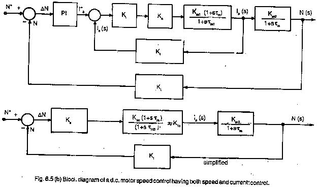
while defining the transfer function, Laplace transform has been used because it transforms all the differential equations to simple algebraic equations. Fig. 6.5 depicts a block diagram of a dc motor in a drive system. The motor has armature voltage as input variable and speed as output variable. The transfer function is written in the block.
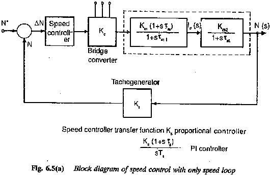
The transfer function is derived from the set of differential equations which describe the behaviour of the system. It, however is not concerned with the internal physical structure of the system. Dissimilar physical systems may have similar transfer functions and also similar dynamic behaviour. The transfer function is in terms of parameters of the system and is a property of the system. It does not depend on the magnitude or nature of the input. The highest power of s in the denominator represents the order of the system.
A simple example is given in the following to show the simplicity afforded by the transfer functions.
Example:
Two RC circuits are connected in cascade, as shown in Fig. 6.6.
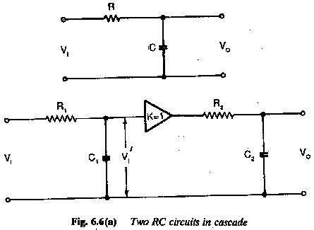
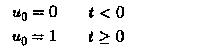
The input is a step voltage
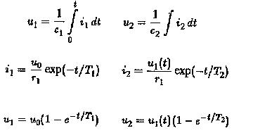
 The amplifier is used to function as dc coupling between them. Determine the time variation of u2. We know
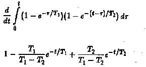
The ratio u2/uo is obtained by evaluating the convolution integral
If one more RC circuit is added in cascade to the given circuit–the evaluation of u2/u0 is very difficult.
On the other hand if transfer function approach is used we have
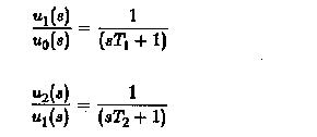
Using these equations, we have
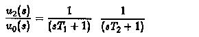
can be very easily evaluated

as using partial fraction expansion.