Circulating Current Scheme for Transformer Protection:
Merz-Price Circulating Current Scheme for Transformer Protection is commonly used for the protection of power transformers against earth and phase faults. The system as applied to transformers is fundamentally the Stine as that for generators but with certain complicating features not encountered in the generator application. The complicating features and their remedial measures are briefed below :
(i) In a power transformer, currents in the primary and secondary are to be compared. As these two currents are usually different, therefore, the use of identical transformers (of same turn ratio) will give differential current and operate the relay even under no load conditions.
The difference in the magnitude of currents in the primary and secondary of power transformer is compensated by different turn ratios of CTs. If T is the turn-ratio of power transformer; then turn-ratio of CTs on the l.v. side is made T times that of the CTs on the h.v. side. Fulfilled this condition, the secondaries of the two CTs will carry identical currents under normal load conditions. Consequently, no differential current will flow through the relay and it remains inoperative.
(ii) There is usually a phase difference between the primary and secondary currents of a 3-phase power transformer. Even if CTs of the proper turn-ratio are used, a differential current may , flow through the relay under normal conditions and cause relay operation.
The correction for phase difference is effected by appropriate connections of CTs. The CTs on one side of the power transformer are connected in such a way that the resultant currents fed into the pilot wires are displaced in phase from the individual phase currents in the same direction as, and by an angle equal to Me:phase shift between the power-transformers primary and secondary currents. The table below shows the type of connections to be employed for CTs in order to compensate for the phase difference in the primary and secondary currents of power transformer.
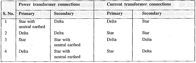
Thus referring to the above table, for a delta/star power transformer, the CTs on the delta side must be connected in star and those on the star side in delta.
(iii) Most transformers have means for tap changing which makes this problem even more difficult. Tap changing will cause differential current to flow through the relay even under normal operating conditions.
The above difficulty is overcome by adjusting the turn-ratio of CTs on the side of the power transformer provided with taps.
(iv) Another complicating factor in Circulating Current Scheme for Transformer Protection is the magnetizing in-rush current. Under normal load conditions, the magnetizing current is very small. However, when a transformer is energized after it has been taken out of service, the magnetizing or in-rush current can be extremely high for a short period. Since magnetizing current represents a current going into the transformer without a corresponding current leaving, it appears as a fault current to differential relay and may cause relay operation.
In order to overcome above difficulty, differential relays are set to operate at a relatively high degree of unbalance. This method decreases the sensitivity of the relays. In practice, advantage is taken of the fact that the initial in-rush currents contain prominent second-harmonic component. Hence, it is possible to design a scheme employing second-harmonic bias features, which, being tuned to second-harmonic frequency only, exercise restrain during energising to prevent maloperation.
While applying circulating current principle for protection of transformers, above precautions are necessary in order to avoid inadvertent relay operation.
Fig. 22.15 shows Merz-Price circulating-current scheme for the protection of a 3-phase delta/delta power transformer against phase-to-ground and phase-to-phase faults. Note that CTs on the two sides of the transformer are connected in star. This compensates for the phase difference between the power transformer primary and secondary. The CTs on the two sides are connected by pilot wires and one relay is used for each pair of CTs.
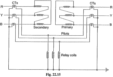
During normal operating conditions, the secondaries of CTs carry identical currents. Therefore, the currents entering and leaving the pilot wires at both ends are the same and no current flows through the relays. If a ground or phase-to-phase fault occurs, the currents in the secondaries of CTs will no longer be the same and the differential current flowing through the relay circuit will clear the breaker on both sides of the transformer. The-protected zone is limited to the region between CTs on the high-voltage side and the CTs on the low-voltage side of the power transformer.
It is worthwhile to note that this scheme also provides protection for short-circuits between turns on the same phase winding. When a short-circuit occurs between the turns, the turn-ratio of the power transformer is altered and causes unbalance between current transformer pairs. If turn-ratio of power transformer is altered sufficiently, enough differential current may flow through the relay to cause its operation. However, such short-circuits are better taken care of by Buchholz relays.