Chopper Resistance in the Rotor Circuit:
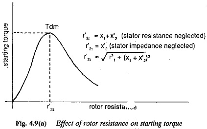
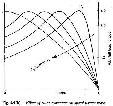
Speed control by means of slip variation can be achieved by employing a variable resistance Chopper Resistance in the Rotor Circuit. From the equations it is clear that the maximum value of torque does not depend upon the value of rotor resistance. However, the rotor resistance influences the slip at which maximum torque occurs. A family of curves has been depicted in Fig. 4.9 for variable resistance in the rotor circuit. For given load conditions it is clear that the speed can be varied. The slip of the motor at any given value of rotor resistance is given by
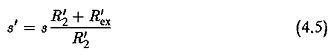
where R′2 is the rotor resistance and R′ex is the resistance included.
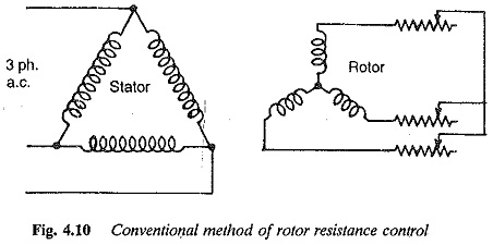
The external resistance can be added very conveniently to the phases of a slip ring rotor. Conventional methods of variation of resistance by means of mechanical contactors are shown in Fig. 4.10. With the development of thyristors it has become possible to use a Chopper Resistance in the rotor circuit. The schematic diagram is shown in Fig. 4.11.
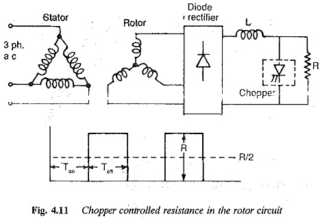
It has been discussed that a resistance connected across the output terminals of a Chopper Resistance can be varied from 0 to R by varying the time ratio of the chopper. When the chopper is always OFF, the supply is always connected to the resistance R. The time ratio in this case is and the effective resistance connected is R. Similarly when the chopper is always ON, the resistance is short circuited. The time ratio in this case is unity and the effective resistance connected is 0. Hence by varying the time ratio from 0 to 1 the value of resistance can be varied from R to 0. The parameter Fig. 4.9 can be the time ratio instead of resistance.
The slip power of the rotor is rectified by a diode rectifier and is fed to the chopper controlled resistance (Fig. 4.11). The torque-speed curves can be drawn for different time ratios. For a time ratio of 1 we get normal characteristic of the motor. For a time ratio of 0 the characteristic corresponds to the one with complete resistance in the rotor circuit. A smoothing inductance L is used in the circuit to maintain the current at a constant value. Any short circuit in the Chopper Resistance does not become effective due to L.
The value of It connected across the Chopper Resistance is effective for all phases and its value can be related to the resistance to be connected in each phase if the conventional method has been used. Thus if Rex is the resistance per phase we have
![]()
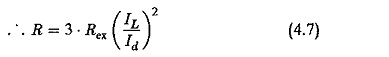 But for a three phase bridge rectifier we have
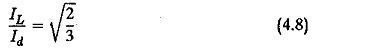
Using this relation in Eq. 4.7 we have
![]()
When once the value of Rex is determined depending upon the range of speed required down to zero speed, the value of Rex and R can be decided based on the torque required at standstill.
The rating of the chopper thyristor decides the maximum rotor current of the motor. The speed control range is limited by the resistance. The method is very inefficient because of losses in the resistance. It is suitable for intermittent loads such as elevators. At low speeds, in particular, the motor has very poor efficiency. Because of the increased rotor resistance, the power factor is better.
The rotor current in this case is non-sinusoidal. The harmonics of the rotor current produce torque pulsations. These have a frequency which is six times the slip frequency. The maximum torque developed is decided by the current carrying capacity.
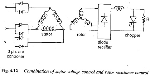
The range of speed control can be increased if a combination of stator voltage control and rotor resistance control is employed. Instead of using a high resistance rotor, a slip ring rotor with external rotor resistance can be used when stator voltage control is used for controlling the speed. The method is depicted in Fig. 4.12.