Capacitance Voltage Dividers:
Capacitance voltage dividers are ideal for measurement of fast rising voltages and pulses. The capacitance ratio is independent of the frequency, if their leakage resistance is high enough to be neglected. But usually the dividers are connected to the source voltage through long leads which introduce lead inductances and residual resistances.
Also, the capacitance used for very high voltage work is not small in dimension and hence cannot be considered as a lumped element. Therefore, the output of the divider for high frequencies and impulses is distorted as in the case of resistance dividers.
Pure Capacitance Dividers:
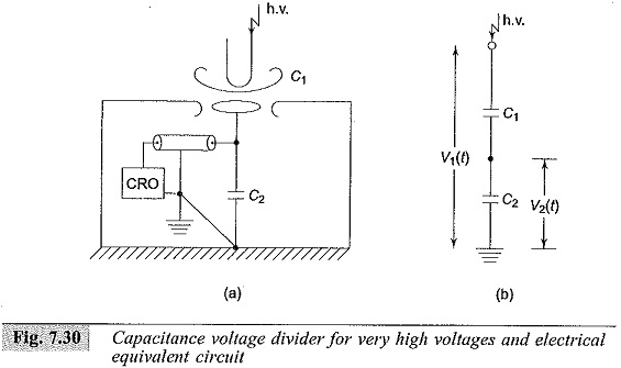
A pure capacitance divider for high voltage measurements and its electrical equivalent network without stray elements is shown in Fig. 7.30. The ratio of the divider
Capacitance C1 is formed between the h.v. terminal of the source (impulse generator) and that of the test object or any other point of measurement. The CRO is located within the shielded screen surrounding capacitance C2. C2 includes the capacitance used, the lead capacitance, input capacitance of the CRO, and other ground capacitances.
The advantage of this connection is that the loading on the source is negligible; but a small disturbance in the location of C2 or h.v. electrode or the presence of any stray object nearby changes the capacitance C1, and hence the divider ratio is affected.
In many cases a standard air or compressed gas capacitor is used which has coaxial cylindrical construction. Accurate ratios that could be calculated up to 1000: 1 have been achieved for a maximum impulse voltage of 350 kV, and the upper frequency limit is about 10 MHz. For smaller or moderately high voltages (up to 100 kV) capacitance dividers are built with an upper frequency limit of 200 MHz.
Another type of design frequently used is to make C1 to consist of a number of capacitors C′1 in series for the given voltage V1. In such cases the equivalent circuit is similar to that of a string insulator unit used in transmission lines (Fig. 7.31).
The voltage distribution along the capacitor chain is non-linear and hence causes distribution of the output wave. But the ratio error is constant and is independent of frequency as compared to resistance dividers. A simplified equivalent circuit is shown in Fig. 7.31b, which can be used if C1 << C2 and Cg << C1. The voltage ratio is
This ratio is constant and gives an error of less than 5% when C1 = 3Cg. This equivalent circuit is quite satisfactory up to 1 MHz.