Brushless DC Motor Drives(Trapezoidal PMAC):
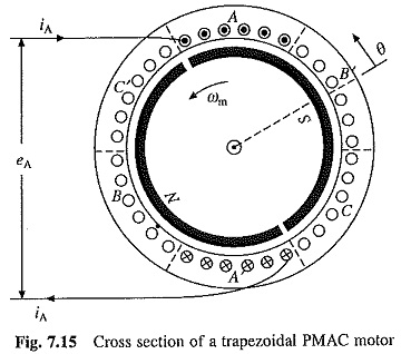
The cross section of a 3-phase 2 pole Brushless DC Motor Drives is shown in Fig. 7.15. It has permanent magnet rotor with wide pole arc. The stator has three concentrated phase windings, which are displaced by 120° and each phase winding spans 60° on each side. The voltages induced in three phases are shown in Fig. 7.17(a). The reason for getting the trapezoidal waveforms can now be explained. When revolving in the counter-clockwise direction, up to 120° rotation from the position shown in Fig. 7.15, all top conductors of phase A will be linking the south pole and all bottom conductors of phase A will be linking the north pole. Hence the voltage induced in phase A will be the same during 120° rotation (Fig. 7.17(a). Beyond 120°, some conductors in the top link north pole and others the south pole. Same happens with the bottom conductors. Hence, the voltage induced in phase A linearly reverses in next 60° rotation. Rest of the waveform of phase A and waveforms of phases B and C can be similarly explained.
An inverter fed trapezoidal PMAC motor drive operating in self-controlled mode is called a brushless dc motor.
Brushless DC Motor Drive for Servo Applications:
A Brushless DC Motor Drives employing a voltage source inverter (VSI) and a trapezoidal PMAC motor is shown in Fig. 7.16(a).
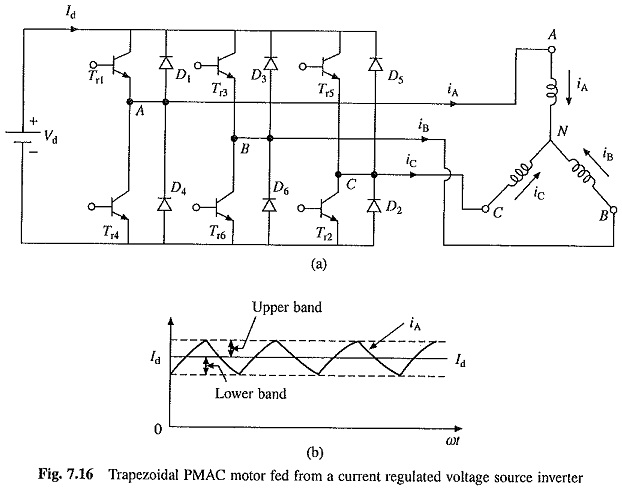
The stator windings are star connected. It will have rotor position sensors, which are not shown in the figure. The phase voltage waveforms for a trapezoidal PMAC motor are shown in Fig. 7.17(a). Let the stator windings be fed with current pulses shown in Fig. 7.17(b). The current pulses are each of 120° duration and are located in the region where induced voltage is constant and maximum. Further, the polarity of current pulses is the same as that of induced voltage. Since the air-gap flux is constant, the voltage induced is proportional to speed of rotor.
![]()
During each 60° interval in Fig. 7.17, current enters one phase and comes out of another phase, therefore, power supplied to the motor in each such interval![]()
Torque developed by the motor
![]()
The waveform of torque is given in Fig. 7.17(c). According to Eq. (7.31) torque is proportional to current Id. It can be shown that a dc current Id flows in the dc link. Regenerative braking operation is obtained by reversing phase currents. This will also reverse the source current Id. Now power flows from the machine to inverter and from inverter to dc source. When speed is reversed, the polarity of induced voltages reverse. With current polarity shown in Fig. 7.17, the drive gives regenerative braking operation, and when current direction is reversed motoring operation is obtained. The current waveforms shown in Fig. 7.17(b) are produced as follows.
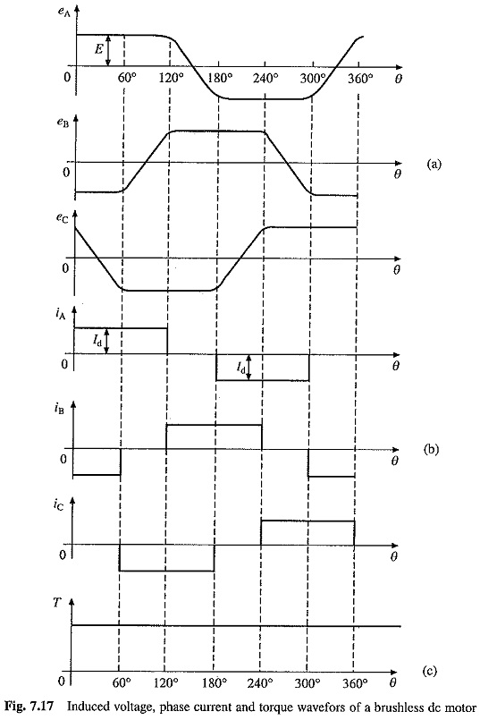
During the period 0∘ to 60∘ , iA = Id and iB = –Id. The current iA enters through the phase A and leaves through the phase B. When transistors Tr1 and Tr6 are on, terminals A and B are respectively connected to positive and negative terminals of the dc source Vd. A current will flow through the path consisting of Vd, Tr1, phase A, phase B and Tr6 and rate of change of current iA will be positive. When Tr1 and Tr6 are turned off this current will flow through a path consisting of phase A, phase B, diode D3, Vd and diode D4. Since the current has to flow against voltage Vd, the rate of change of iA will be negative. Thus, by alternately turning on and off Tr1 and Tr6 phase A current can be made to follow the reference current Id within a hysteresis band as shown in Fig. 7.16(b). By reducing the band sufficiently nearly a dc current of desired value can be produced.
The operation for other 60° intervals can be similarly explained. For properly placing the current pulses with respect to induced voltages, or identification of these sixty-degree intervals, signals are generated by rotor position sensors. In all six rotor angular positions are required to be detected per cycle of the induced voltage. The Hall effect sensors can detect the magnitude and direction of a magnetic field. Hence three Hall-effect sensors can detect the six rotor positions. The sensors are mounted at 60° electrical interval and aligned suitably with the stator winding. Optical sensors are also available. Sensors used with trapezoidal PMAC motor are cheaper compared to those required with sinusoid PMAC motor. Since trapezoidal motor is also cheaper, the drive has much lower cost. Although dynamic response is comparable, the torque ripple is considerably higher in this drive.
Torque ripple is caused due to induced voltage not being exactly trapezoidal and inverters inability to produced rectangular current waveforms. The trapezoidal PMAC drive is widely used in servo drives, except in high performance drives where sinusoidal PMAC motor drive is preferred.
There are large number of similarities between the inverter fed trapezoidal PMAC motor and a dc motor. Like a dc motor, voltage induced is proportional to speed [Eq. (7.30)], torque is proportional to armature current [Eq. (7.31)], and stator and rotor fields remain stationary with respect to each other. However, it does not have brushes and associated disadvantages, hence inverter-fed trapezoidal PMAC motor is commonly known as brushless dc motor. This motor is also conceived as electronically commutated dc motor, because the inverter here performs the same function as the brushes and commutator in a dc motor, i.e. to shift currents between armature conductors to keep the stator and rotor fields stationary (and in quadrature) with respect to each other.
Low Cost Brushless DC Motor Drives:
One of the important point about Brushless DC Motor Drives is that by integration of converter/inverter with motor, the drive is simplified substantially, resulting in simpler control and substantial reduction in cost. While three phase machines are used in majority applications, single phase and four phase machines are also employed. Similarly wide variety of converters/inverters is used. The motors are fed by current pulses and also by voltage pulses with a current limit only to make sure that the current does not exceed ratings of converter and motor. Two such drives are described below.
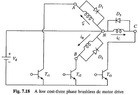
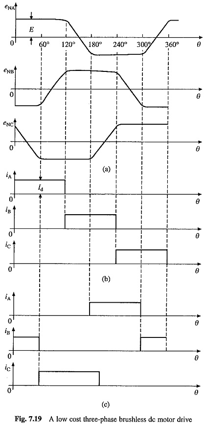
A low cost drive employing a 3-phase trapezoidal PMAC motor is shown in Fig. 7.18. It employs only three transistor and three diode converter, which can supply only positive currents or voltages to three motor phases. Induced voltages and current supplied for motoring and braking operations are shown in Fig. 7.19. When 120° positive current pulses as shown in Fig. 7.19(b) are supplied to the motor, motoring operation is obtained in counter clockwise direction. When these pulses are shifted by 180°, as shown in Fig. 7.19(c), braking operation is obtained. Motoring and braking operations for clockwise rotation is obtained by timing the pulses as shown in Fig. 7.19(c) and (b), respectively. Each phase is essentially supplied by a chopper. The phase NA current is controlled by Tr1 and D1. When Tr1 is on source Vd is connected across winding NA and rate of change of iA is positive. When Tr1 is turned off, current iA freewheels through diode D1 and rate of change of iA is negative. Thus during the period for 0° to 120°, Tr1 can be alternately turned on and off so that current iA is made to follow a rectangular reference current i*A within a hysteresis band.
As compared to the drive of Fig. 7.16, the torque produced by this drive for a given value of Id will be half, giving slower dynamic response. The drive also has higher torque ripple.
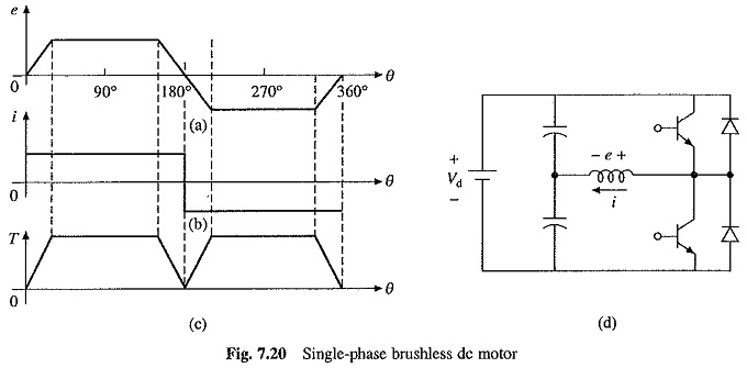
Let us also examine a single phase Brushless DC Motor Drives. Let the motor has wide pole are as shown in Fig. 7.15 and a single concentrated phase winding with a spread of 60° on either side. Let θ be measured from the instant when the axis of phase coincides with the axis of the rotor pole, then the voltage induced in the phase winding will have waveform as shown in Fig. 7.20. Let the motor be supplied from a half bridge single phase converter shown in Fig. 7.20(d) with a rectangular current waveforms shown in Fig. 7.20(6). Then the torque produced by the motor will have waveform shown in Fig. 7.20(c). Although the torque has a large ripple, when running at high speeds the torque ripple will be filtered out by the inertia of motor load system, giving a uniform speed.
Important Features and Applications:
Due to the absence of brushes and commutator, Brushless DC Motor Drives have a number of advantages compared to conventional dc motors. They require practically no maintenance, have long life, high reliability, low inertia and friction, and low radio frequency interference and noise. Due to low inertia and friction, they have a faster acceleration and can be run at much higher speeds – up to 100,000 rpm and higher are common. Because armature windings are on the stator, cooling is much better, i.e. higher specific outputs can be obtained. These motors have high efficiency, exceeding 75% whereas wound field motors of low power ratings have much lower efficiency. The disadvantages compared to conventional dc motors are high cost and low starting torque. The size of a brushless dc motor is nearly the same as of conventional dc motor.
The Brushless DC Motor Drives finds applications in turn table drives in record players, tape drive for video recorders, spindle drives in hard disk drives for computers, and low cost and low power drives in computer peripherals, instruments and control systems. They also have applications in the fields of aerospace, e.g. gyroscope motors, and biomedical like cryogenic coolers and artificial heart pumps. They are also used for driving cooling fans for electronic circuits and heat sinks.