Braking of Induction Motor:
The three types of Braking of Induction Motor, namely regenerative, dynamic and counter current braking can be accomplished with induction motors also.
Regenerative braking
When the rotor of an induction motor runs faster than the stator field the slip becomes negative and the machine generates power. Therefore, whenever the motor has a tendency to run faster than the rotating field, regenerative braking occurs and the K.E. of the rotating parts is returned to the mains. The speed-torque curve extends to the second quadrant (Fig. 1.47). The speed of the motor decreases. The braking torque makes the motor run at constant speed, arresting its tendency to rotate faster. Due to the effects of stator resistance, the maximum torque developed during regeneration is greater than the maximum torque during motoring. In hoists and cranes the drive motor has a tendency to run faster than the synchronous speed. This situation occurs when the hoist is raising an empty cage. Due to the counterweight, the case may acquire dangerous speeds. The transition takes place almost automatically and a torque is developed to arrest the acceleration and regeneration takes place. This kind of operation is also possible when the load overhauls the motor during the descent of the load. Automatic regeneration arrests undue acceleration. Rotor resistance control may be employed to get better braking torque.
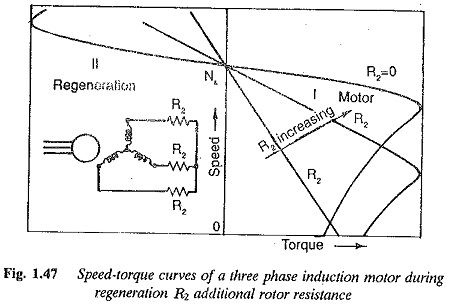
Regenerative braking is also possible with a pole change motor when the speed is changed from high to low. It can easily be accomplished in a variable frequency drive also. By decreasing the frequency of the motor momentarily, the synchronous speed decreases and conditions favorable to regeneration take place.
During regenerative braking there is a possibility of dangerous speeds if the operating point during braking falls in the unstable portion of the characteristic. This happens if the load torque is greater than the breakdown torque of the motor. The torque developed cannot brake the motor and undue acceleration takes place. This possibility can be eliminated by means of a high resistance in the rotor.
Dynamic braking
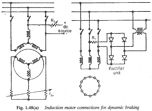
Dynamic braking is employed to brake a non-reversing drive. The stator is transferred from ac mains to dc mains (Fig. 1.48(a)). The dc flowing through the stator sets up a stationary field. This induces rotor currents which produce a torque to bring the rotor to rest quickly. The torque developed and the retardation during braking may be controlled by the amount of dc power. Additional resistances r1 and r2e in the stator and rotor circuits respectively control the dc excitation and braking torques.
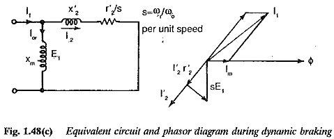
The equivalent circuit and phasor diagram of the motor during dynamic braking are shown in Fig. 1.48(c). When the stator is fed from dc the mmf produced is stationary. This mmf depends upon the stator connections for feeding dc, the number of turns, and the current. The possible connections of the stator for feeding dc are shown in Fig. 1.49. The dc equivalent current can be determined by equating the mmfs produced by this equivalent current and the ac current.
The equivalent primary current is responsible for the magnetisation and the secondary current for the torque. The torque is given by
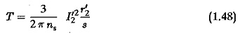
where s is p.u. slip.
From the equivalent circuit we have
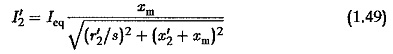
Also, from the phasOr diagram we have
![]()
from which Im can be determined. The value of xm is given by
![]()
The torque is
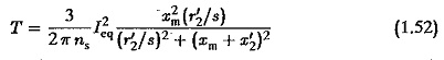
The torque slip curve can be determined using this expression. The maximum torque occurs at a slip
and the maximum braking torque is
The characteristic can also be drawn using the relation
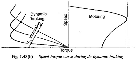
The braking torque is proportional to I21.. However saturation plays its own role and there is a depletion of the torque. The effect of r′2 is similar to the effects during motoring, i.e. it does not change the value of Tmb, but changes the value of the speed at which Tmb occurs.. Typical speed-torque curves are shown in Fig. 1.48.
The values of I1 and r′2 are controlled to provide the desired braking. The former is limited by R1. This method is applied commonly to brake the motors driving active loads. Dynamic braking is employed in conjunction with automatic control. The Braking of Induction Motor is more popular in hoists than the dc motor, due to this feature.
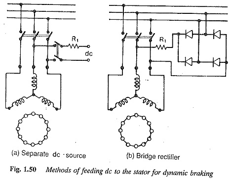
The methods of feeding a dc supply to the stator are depicted in Fig, 1.50. It may be provided by a dc supply using a limiting resistor R1 in the circuit for controlling dc excitation. Torque control is achieved by rotor resistance variation. Alternatively, an ac supply may be rectified by means of a diode rectifier and the resulting dc may be fed to the motor.
In ac dynamic braking the stator is switched to a capacitance bank. The machine runs as a self excited induction generator. All the mechanical energy is dissipated as electrical energy in the rotor resistance. This method is uneconomical, due to the cost of the capacitors.
Counter current braking
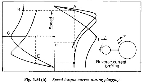
By changing the phase sequence of the input to an Braking of Induction Motor motor, the direction of the stator field can be reversed. In practice this is done by interchanging the supply to any two terminals of the motor (Fig. 1.51(a)). A braking torque is developed and the motor comes to rest very fast. The motor must be switched off from the mains when zero speed is approached. Else the torque developed accelerates the motor in the reverse direction. This method is also called plugging.
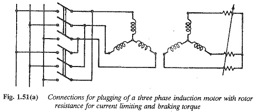
When the motor is plugged, the induced voltage E in the armature and the applied voltage V aid each other and the current during braking is caused by E + V. This may result in very high currents, which are limited by the high rotor resistance, and also effectively increase the braking torque.
The speed-torque curve of an Braking of Induction Motor motor can be modified by varying the rotor resistance. The maximum torque point can be made to occur in the range of slips 1-2, where the torque developed tends to brake the rotor. This torque can also be used to arrest the tendency of the rotor to accelerate due to one reason or the other (e.g. load overhauling the motor or a hoist raising the empty cage). A high resistance is introduced in the rotor, so that the operating point shifts to the fourth quadrant. The braking torque developed prevents any acceleration of the rotor, and the rotor works at uniform speed (Fig. 1.51(b)).
If the motor is operating at a slip a at the instant of plugging, the total braking torque is the sum of the plugging torque at (2 — s) and the load torque
![]()
Tp may be controlled by a variable rotor resistance which limits the braking current.