Binary Number System in Digital Electronics:
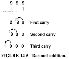
Binary Number System in Digital Electronics – The decimal number system, using the base or radix 10, is familiar to most people. The digits for the system are defined as the non-negative integers which are smaller than the radix. For the decimal system, therefore, the digits are 0 to 9. This means that when one column of numbers increases beyond 9, the highest single digit, a carry is made to the next column while the first column returns to zero. The number 10 results. When the first two columns reach 99, carries are made from the first column to the second column and from the second column to the third column and the number 100 results. This familiar procedure is illustrated in Figure 14-5.
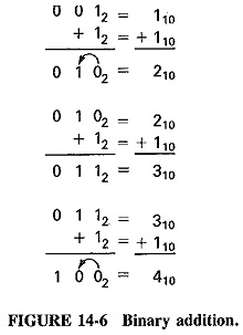
The radix of the binary number system is the number 2, so that the digits of the binary system are limited to only two, 0 and 1. Therefore, when 1 is added to a binary number column, the first count changes the column from 0 to 1. When one more is added, the radix has been reached, so a carry is accomplished to the next column as shown in Figure 14-6. The binary number 10, which has the decimal value of 2, results. If 1 is added to the 102, the binary number 11, which has a decimal value of 3, is obtained. Adding one to 112 requires a carry from column one to column two and a carry from column two to column three. The resulting binary number is 100, which has a decimal value of 4.
Binary/Decimal conversion:
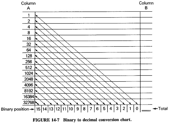
The decimal values of the different places in a 16-bit Binary Number System in Digital Electronics. They can be used to determine the decimal value of Binary Number System in Digital Electronics. Figure 14-7 demonstrates a chart that makes it possible to determine the decimal equivalent of each 1 in a binary number, and to add these decimal numbers together to determine the decimal value of the binary number. A binary word is entered beneath the binary position line. For each “1” in the binary word, the diagonal is followed to the value in column A. These values are entered in the blanks under column B and when added provide the decimal value of the binary word.
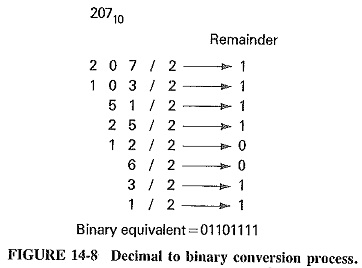
Conversion from decimal to binary uses a different process, whereby the decimal number is divided by two and the remainder recorded each time, as shown in Figure 14-8. Since each division is by 2, a remainder of either 1 or 0 must be obtained. The conversion is complete when the division by two cannot continue.
Binary Addition and Subtraction:
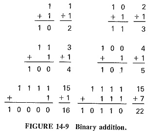
Addition of Binary Number System in Digital Electronics follows the four simple rules shown below:

Examples of binary addition are given in Figure 14-9.
Subtraction of binary numbers can be accomplished by using standard subtraction procedures, but this is not usually done in computer and data transmission systems. Instead, subtraction is accomplished by adding the 2s complement of the subtrahend to the minuend. The 2s complement is defined as the number which when added to the original number will result in a sum of unity. The 2s complement can be obtained in a two-step process. First, the is complement of the subtrahend is obtained by converting each digit of the subtrahend to the opposite value. The 2s complement is then obtained by adding 1 to the 1s complement. The following example demonstrates the process.
The important point about the binary number system is to recognize that it can be used to represent any decimal number, As indicated, all binary numbers will consist entirely of 0s and 1s. This is advantageous for use in digital electronic systems which are designed to utilize binary codes, When codes are based on the Binary Number System in Digital Electronics, they are computable; that is, they can be added and subtracted or evaluated to determine which is larger.