Bias Circuit Thermal Stability:
VBE and ICBO Variations – Many transistor circuits are required to operate over a wide temperature range. So, another aspect of bias circuit stability is Bias Circuit Thermal Stability, or how stable IC and VCE remain when the circuit temperature changes.
Measures to deal with the effects of hFE variations have already been discussed. These apply whether the different hFE values are due to temperature changes or to hFE differences from one transistor to another.
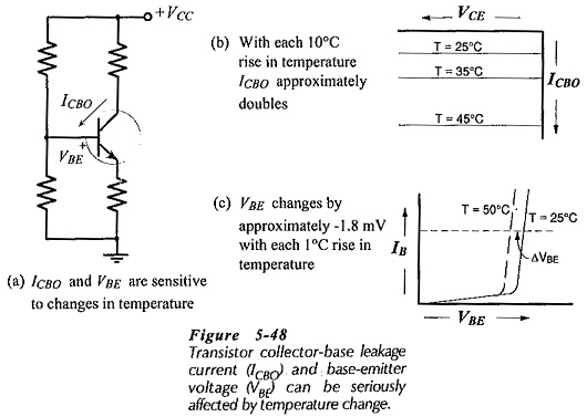
The base-emitter voltage (VBE) and the collector-base reverse, saturation current (ICBO) are the two temperature-sensitive quantities that largely determine the Bias Circuit Thermal Stability of a transistor circuit, [see Fig. 5-48(a)]. The base-emitter and collector-base pn-junctions have the temperature characteristics. For a silicon transistor, VBE changes by approximately -1.8 mV/°C, and ICBO approximately doubles for every 10°C rise in temperature. These effects are illustrated by the characteristics in Fig. 5-48(b) and (c).
An increase in ICBO causes IC to be larger, and the IC increase raises the collector-base junction temperature. This, in turn, results in a further increase in ICBO. The effect is cumulative, so that the end result might be a substantial collector current increase. This could produce a significant shift in the circuit Q-point, or in the worst case, IC might keep on increasing until the transistor collector-base junction overheats and burns out. This effect is known as thermal runaway. Measures taken to avoid thermal runaway are similar to those required for good bias stability against hFE spread.
Changes in VBE may also produce significant changes in IC and consequently in the circuit Q-point. However, because of the possibility of thermal runaway, ICBO changes are the most important. The Bias Circuit Thermal Stability is assessed by calculating a stability factor.
Stability Factor:
The stability factor (S) of a circuit is the ratio of the change in collector current to the change in collector-base leakage current.
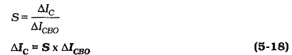
The value of S depends on the circuit configuration and on the resistor values. The minimum values of S is 1. This means that if ICBO increases by 1 μA IC will increase by 1 μA. If a circuit has an S of 50, then ΔIC = 50 x ΔICBO. A stability factor of 50 (or larger) is considered poor, while a factor of 10 or less is considered good.
An equation for the stability factor of a bias circuit can be derived by writing an equation for the circuit IC and investigating the effect of ICBO change. The stability factors for the three basic bias circuit types (reproduced in Fig. 5-49) can be shown to be:
For base bias,
![]()
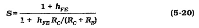
For collector-to-base bias,
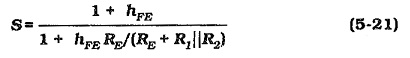
For voltage divider bias,
The change in ICBO over a given temperature range can be calculated by recalling that ICBO doubles for every 10°C increase in temperature. The temperature change (ΔT) is divided by 10 to give the number of 10°C changes (n). If the starting level of collector-base leakage current is ICBO(1), the new level is,
![]()
The ICBO change and the circuit stability factor can be used to determine the change in IC, (Eq. 5-18). Then the resulting VCE change can be investigated.
Effect of VBE Changes:
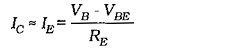
Consider the voltage divider bias circuits in Fig. 5-51(a) and (b), which each have VCC = 12 V and IC = 1 mA. From Eq. 5-9,
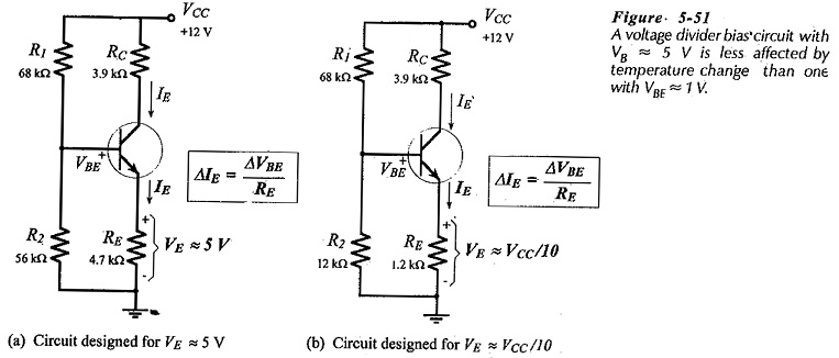
Assuming that VB remains substantially constant, an equation for IC change with VBE change can be written:
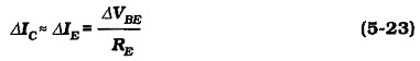
As discussed already, the emitter resistor voltage should typically be selected as 5 V, (VE >> VBE). This is to ensure that IC is not significantly affected by changes in VBE. Thus, the circuit in Fig. 5-51(a) (with VE ≈ 5 V) has greater stability against VBE changes than the one in Fig. 5-51(b) which was designed for VE = VCC/10,(VE = 1.2V).
Diode Compensation:
The use of a diode to compensate for VBE changes is illustrated in Fig. 5-52. In this case,
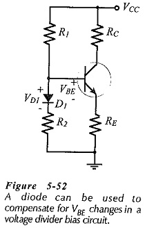
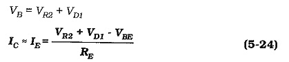
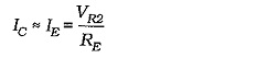
When VBE changes by ΔVBE, the diode voltage changes by an approximately equal amount (ΔVD1). ΔVBE and ΔVD1 tend to cancel each other, leaving IC largely constant at,
Base bias and collector-to-base bias are less affected by VBE changes than voltage divider bias. This can easily be demonstrated by considering the equations for the base current in each case.