Balanced Earth Fault Protection:
In small-size alternators, the neutral ends of the three-phase windings are often connected internally to a single terminal. Therefore, it is not possible to use Merz-Price circulating current principle described above because there are no facilities for accommodating the necessary current transformers in the neutral connection of each phase winding. Under these circumstances, it is considered sufficient to provide protection against earth-faults only by the use of Balanced Earth Fault Protection scheme. This scheme provides no protection against phase-to-phase faults, unless and until they develop into earth-faults, as most of them will.
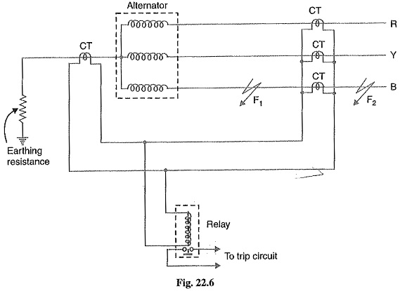
Schematic arrangement: Fig. 22.6 shows the schematic arrangement of a Balanced Earth Fault Protection for a 3-phase alternator. It consists of three line current transformers, one mounted in each phase, having their secondaries connected in parallel with that of a single current transformer in the conductor joining the star point of the alternator to earth. A relay is connected across the transformers secondaries. The protection against earth faults is limited to the region between the neutral and the line current transformers.
Operation: Under normal operating conditions of Balanced Earth Fault Protection, the currents flowing in the alternator leads and hence the currents flowing in secondaries of the line current transformers add to zero and no current flows through the relay. Also under these conditions, the current in the neutral wire is zero and the secondary of neutral current transformer supplies no current to the relay.
If an earth-fault develops at F2 external to the protected zone, the sum of the currents at the terminals of the alternator is exactly equal to the current in the neutral connection and hence no current flows through the relay. When an earth-fault occurs at F1 or within the protected zone, these currents are no longer equal and the differential current flows through the operating coil of the relay. The relay then closes its contacts to disconnect the alternator from the system.
Stator Inter Turn Protection:
Merz-price circulating-current system protects against phase-to-ground and phase-to-phase faults. It does not protect against turn-to-turn fault on the same phase winding of the stator. It is because the current that this type of fault produces flows in a local circuit between the turns involved and does not create a difference between the currents entering and leaving the winding at its two ends where current transformers are applied. However, it is usually considered unnecessary to provide protection for inter-turn faults because they invariably develop into earth-faults.
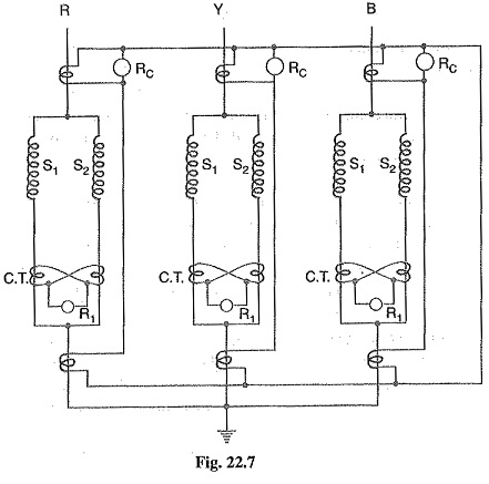
In single turn generator (e.g. large steam-turbine generators), there is no necessity of protection against inter-turn faults. However, inter-turn protection is provided for multi-turn generators such as hydro-electric generators. These generators have double-winding armatures (i.e. each phase winding is divided into two halves) owing to the very heavy currents which they have to carry. Advantage may be taken of this necessity to protect inter-turn faults on the same winding. Fig, 22.7 shows the schematic arrangement of circulating-current and inter-turn protection of a 3-phase double wound generator. The relays RC provide protection against phase-to-ground and phase-to-phase faults whereas relays R1 provide protection against inter-turn faults.
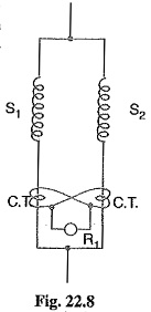
Fig. 22.8 shows the duplicate stator windings S1 and S2 of one phase only with a provision against inter-tum faults. Two current transformers are connected on the circulating-current principle. Under normal conditions, the currents in the stator windings S1 and S2 are equal and so will be the currents in the secondaries of the two CTs. The secondary current round the loop then is the same at all points and no current flows through the relay R1. If a short-circuit develops between adjacent turns, say on S1, the currents in the stator windings S1 and S2 will no longer be equal. Therefore, unequal currents will be induced in the secondaries of CTs and the difference of these two currents flows through the relay R1. The relay then closes its contacts to clear the generator from the system.