Approximate Circuit Model of an Induction Motor:
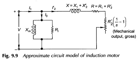
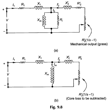
An Approximate Circuit Model of an induction motor, which results in considerable computational ease in analysis, is obtained by shifting the shunt branch in Fig. 9.8(a) to the input terminals as shown in Fig. 9.9. This step is not so readily justified as in a transformer owing to the relative magnitude of the exciting current (also referred to as the magnetizing current) which, because of the presence of the air-gap, may be as large as 30-50% of the full-load current.
Further, the primary leakage reactance is also necessarily higher in an induction motor compared to a transformer and so ignoring the voltage drop in primary reactance is not quite justified. It is, therefore, pointed out here that the results obtained by this model are considerably less accurate than that obtained from the models of Fig. 9.8(a) and (b).
The parameters of the induction motor models as presented above are obtained from no-load and blocked-rotor tests.
It is easily seen from Fig. 9.9 that because of the magnetizing shunt branch which draws current I0 at almost 90° lagging, the pf at which the motor operates at full-load is low about 0.8. At light load (small I′2) the machine power factor is much lower. This is the inherent problem of the induction motor because of the presence of the air-gap in the magnetic circuit and the fact that the excitation current must be drawn from the mains (stator side).