Antenna Coupling:
Antenna Coupling : Low and medium frequency antennas are the ones least likely to be of resonant effective height and are therefore the least likely to have purely resistive input impedances. This precludes the connection of such an antenna directly, or via transmission line, to the output tank circuit of a transmitter. Some sort of matching network will have to be used.
General Considerations:
A coupling network, or Antenna Coupling, is a network composed of reactances and transformers, which may be lumped or distributed. The coupling network is said to provide impedance matching and is employed for any or all of the following reasons:
- To tune out the reactive component of the antenna impedance, making the impedance appear resistive to the transmitter; otherwise detuning will take place when the antenna is connected. This function involves the provision of variable reactances.
- To provide the transmitter (and also transmission line, if used) with the correct value of load resistance. This involves having one or more adjustable transformers.
- To prevent the illegal radiation of spurious frequencies from the system as a This function requires the presence of filtering, generally low-pass, since the spurious frequencies are most likely to be harmonics of the transmitter’s frequency.
It should be noted that the first two functions apply to low- and medium-frequency transmitters. The last requirement applies equally at all frequencies. One other consideration sometimes applies, specifically to transmitters in which the output tank is series-fed and single-tuned. Here the Antenna Coupling must also prevent the dc supply from reaching the antenna. If this is not done, two serious problems will arise; antenna insulation difficulties and danger to operators. The danger will be caused by the fact that, where RF burns are serious and painful, those coming from the dc high-voltage supply to the power amplifier are fatal.
Selection of Feed Point:
The half-wave dipole antennas presented so far have mostly been drawn with the feeding generator connected to the center. Although many practical antennas are fed in this way, the arrangement is by no means essential. The point at which a particular antenna is fed is determined by several considerations, of which perhaps the most important is the antenna impedance. This varies from point to point along the, antenna, so that some consideration of different options is necessary.
Voltage and Current Feed:
When a dipole has an effective length that is resonant (equal to physical length), the impedance at its center will be purely resistive. This impedance will be high if there is a current node at the center, as with a full-wavelength antenna, or low if there is a voltage node at the center, as with a half-wave dipole. An antenna is said to be current-fed if it is fed at a point of current maximum. A center-fed half-wave dipole or Marconi antenna is current-fed. A center-fed full-wave antenna is said to be voltage-fed.
Feed-point impedance:
The current is maximum in the center and at the ends of a half-wave dipole in space, or a grounded quarter-wave Marconi, whereas the voltage is just the reverse. In a practical antenna the voltage or current values will be low (not zero) so that the antenna impedance will be finite at those points. We have several thousands of ohms at the ends, and 72 Ω in the center, both values purely resistive. Broadcast antennas are often center-fed in practice, 72 Ω being a useful impedance from the point of view of transmission lines. It is for this reason that antennas, although called grounded, are often insulated from the ground electrically. The base of the antenna stands on an insulator close to the ground and is fed between base and ground, i.e., at the center of the antenna-image system.
Antenna Couplers:
Although all antenna couplers must fulfill the three requirements and there are still individual differences among them, governed by how each antenna is fed. This depends on whether a transmission line is used, whether it is balanced or unbalanced and what value of standing-wave ratio is caused by the antenna.
Directly Fed Antennas:
These antennas are coupled to their transmitters without transmission lines, generally for lack of space. To be of use, a line connecting an antenna to its transmitter ought to be at least a half-wave in length, and at least the first quarter-wave portion of it should come away at right angles to the antenna. This may be difficult to accomplish, especially at low frequencies, for shipboard transmitters or those on tops of buildings.
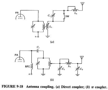
Figure 9-18a shows the simplest method of direct coupling. The impedance seen by the tank circuit is adjusted by moving coil L1, or by changing the number of turns with a traveling short circuit. To tune out the antenna reactance, either C1 or L1 is shorted out, and the other component is adjusted to suit. This is the simplest coupling network, but by no means the best, especially since it does not noticeably attenuate harmonics.
The pi (π) coupler of Figure 9-18a is a much better configuration. It affords a wider reactance range and is also a low-pass filter, giving adequate’harmonic suppression. It will not provide satisfactory coupling if the antenna is very short, due to its capacitive input impedance. It is better, under those conditions, to increase the height of the antenna.
Coupling with a transmission line:
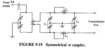
The requirements are similar to those already discussed. Balanced lines, and therefore balanced coupling networks, are often used, as shown in Figure 9-19. The output tank is tuned accordingly, and facilities must be provided to ensure that the two legs of the Antenna Coupling can be kept balanced. At higher frequencies distributed components such as quarter-wave transformers and stubs can be used.
Impedance Matching with Stubs and Other Devices:
When the characteristic impedance of a transmission line is not equal to the impedance of an antenna, quarter- or half-wave stubs can be utilized as matching transformers. These stubs are generally constructed from a low-loss metallic material of predetermined length and are connected as shown in Figure 9-20a.
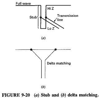
This method of matching the antenna to the feed line is accomplished simply by connecting the coax, or the twin lead, to the stub and sliding the connections up or down the stub until the proper SWR is indicated by a meter connected in the system. To determine the characteristic impedance of the matching section, Equation (9-7) can be used.
![]()
where
Zs = impedance of the transmission line
Zr = impedance of the antenna
It should be noted that the term reflected impedance is commonly used with these matching devices.
Figure 9-20a shows a quarter-wave (λ/4) stub acting as a matching transformer between a coaxial feed line and an end fed half-wave (λ-2) antenna. As shown in the figure, when the feed line end is shorted (0 Ω), it is said to reflect the opposite of its termination impedance, each λ/4, i.e., ∞, which can match the high end impedance of the antenna.
Another commonly used method of impedance matching, especially where cost may be a factor, is the delta (Δ) match. This Antenna Coupling method is accomplished by spreading the ends of the feed line (Figure 9-20b) and adjusting the spacing until optimum performance is reached. This method has some disadvantages but is quick and inexpensive.