Amplification in Transistor:
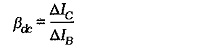
Current Amplification in Transistor – We already know that a transistor can be used for current amplification. A small change in the base current (ΔIB) produces a large change in collector current (ΔIC) and a large emitter current change (ΔIE), [see Fig. 4-16(a) and (b)]. Rewriting Eq. 4-5, the current gain from the base to collector can be stated in terms of current level changes
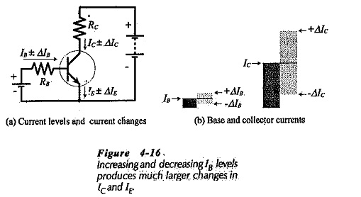
The increasing and decreasing levels of input and output currents may be defined as alternating quantities. In this case, small (lower-case) letters are used for the subscripts. Thus, Ib is an ac base current, Ic is an ac collector current, and Ie is an ac emitter current. The alternating current gain from base to collector may now be stated as,
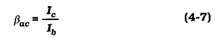
As in the case of dc current gain, two parameter symbols are available for common-emitter ac current gain; βac and hfe. Either symbol may be used, but, once again, hfe is the symbol employed on transistor data sheets.
Voltage Amplification:
Refer to the circuit in Fig. 4-17(a) and assume that the transistor (Q1) has βdc = 50. Note that the 0.7 V dc voltage source (VB) forward biases the transistor base-emitter junction. An ac signal source (υi) in series with VB provides a ± 20 mV input voltage. The transistor collector is connected to a 20 V dc voltage source (VCC) via the 12 kΩ collector resistor (R1).
If Q1 has the IB/VBE characteristic shown in Fig. 4-17(b), the 0.7 V level of VB produces a 20 μA base current. This gives,![]()
The dc level of the transistor collector voltage can now be calculated as,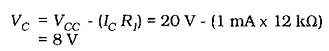
The VC and IC levels are shown on Fig. 4-17(a).
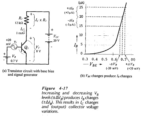
While the ac input voltage (υi) is zero, the transistor collector voltage remains at 8 V. When υi causes a base voltage variation (ΔVB) of ±20 mV, the base current changes by ±5 μA, as shown in Fig. 4-17(b). The IB change produces a collector current change.
![]()
Figure 4-18(a) shows that ΔIC causes a change in the voltage drop across R1, and thus produces a variation in the transistor collector voltage.
![]()
The circuit ac input is the base voltage change (ΔVB), and the ac output is the collector voltage change (ΔVC). Because the output is greater than the input, the circuit has a voltage gain; it is a voltage amplifier. The voltage gain (Aυ) is the ratio of the output voltage to the input voltage.
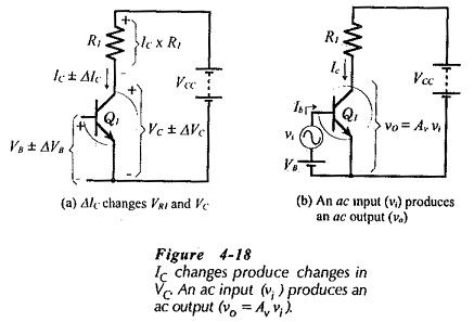
As already discussed for current changes, the increasing and decreasing levels of voltage can be referred to as no quantities. The ac signal voltage (υi) produces the ac base current (Ib), and this generates the ac collector current (IC) which produces the ac voltage change across R1, [see Fig. 4-18(b)]. The equation for ac voltage gain is,
Substituting the ac quantities for Fig. 4-17(a) into Eq. 4-8 gives Aυ = 150 once again.