AC Field Strength Meter:
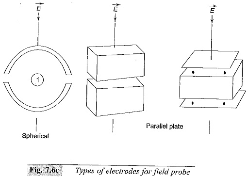
AC Field Strength Meter is usually measured by introducing a small fixed capacitance probe into the field area and measuring the induced charge on it. Since the electric field between the plates of the capacitor is proportional to the charge induced on the plates of the capacitor and varies because of the variation of the AC electric field, the capacitive current is a measure for the field. Usually the electrodes of the field (capacitive) probe are spherical or parallel plates as shown in Fig. 7.6(c).
The charge Q induced on the surface of a conductor in an electric field E for a spherical electrode is given by
![]()
The surface change density over a hemisphere is given by
![]()
and integrating over the surface area gives the above value
If the electric field is AC and given by E sin ωt, the current through the probe is given by
![]()
The rms value of the current is proportional to E. Depending on the type of probe electrode used the value of K is determined and is included. The current is usually measured through a rectifier meter: This meter can be used over a wide range of frequencies but must be re-calibrated for that frequency. The accuracy of the meter is about 0.5% and depends on the harmonic content, atmospheric conditions like temperature, humidity, etc, and the position or location of the meter in the electric field.
Measurement of Ripple Voltage in D.C. Systems:
It has been discussed in the previous chapter that d.c. rectifier circuits contain ripple, which should be kept low (<< 3%). Ripple voltages are a.c. voltages of non-sinusoidal nature, and as such oscillographic measurement of these voltages is desirable. However, if a resistance potential divider is used along with an oscilloscope, the measurement of small values of the ripple δV will be inaccurate.
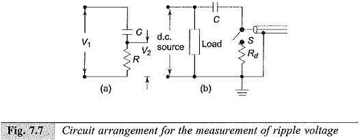
A simple method of measuring the ripple voltage is to use a capacitance-resistance (C-R) circuit and measure the varying component of the a.c. voltage by blocking the d.c. component. If V1 is the d.c. source voltage with ripple (Fig. 7.7a) and V2 is the voltage across the measuring resistance R, with C acting as the blocking capacitor, then
![]()
The condition to be satisfied here is to ω CR >>1.
Measurement of Ripple with CRO:
The detailed circuit arrangement used of this purpose is shown in Fig. 7.7b. Here, the capacitance ‘C’ is rated for the peak voltage. It is important that the switch ‘S’ be closed when the CRO is connected to the source so that the CRO input terminal does not receive any high voltage signal while ‘C’ is being charged. Further, C should be larger than the capacitance of the cable and the input capacitance of the CRO, taken together.