3 Phase Induction Motor Construction:
A converter fed 3 Phase Induction Motor Construction has the following advantages over a line fed motor:
1.Smooth start up is guaranteed by variable frequency starting from a low
2.Soft starting and acceleration at constant current and torque are possible.
3.The network is no longer subjected to a high switching surge current as with the direct switch ON of cage 3 Phase Induction Motor Construction, and as such, special starting equipment can be omitted even at high ratings.
4.High moments of inertia can be accelerated without need to over dimension the motor.
5.The converter acts as a decoupling device. Therefore, feedback from the motor to the point of short circuit does not take place, when line short circuits The short circuit rating, on the basis of which the switchgear has to be overdimensioned is therefore low, permitting a saving to be made.
As has already been stated, the 3 Phase Induction Motor Construction speed can be controlled by supplying the stator a variable voltage, variable frequency supply using static frequency converters. Speed control is also possible by feeding the slip power to the supply system using converters in the rotor circuit. Basically one distinguishes two different methods of speed control.
1.Speed control by varying the slip frequency when the stator is fed from a constant voltage, constant frequency mains.
2.Speed control of the motor using a variable frequency variable voltage, motor operating at constant rotor frequency.
Speed control by variation of slip frequency is obtained by the following ways:
1.Stator voltage control using a three-phase voltage controller.
2.Rotor resistance control using a chopper controlled resistance in the rotor circuit.
3.Using a converter cascade in the rotor circuit to recover slip energy.
4.Using a cycloconverter in the rotor circuit.
Control of an Induction Motor by Stator Voltage Variation (Using a Three Phase Voltage Controller)
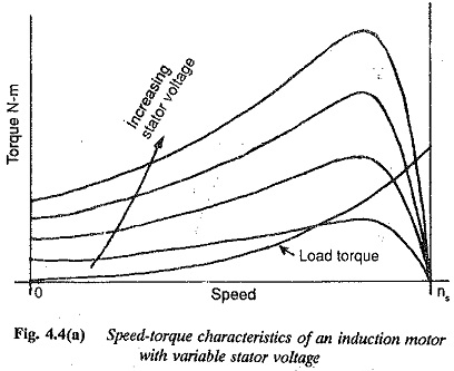
It is very well known that the torque of an 3 Phase Induction Motor Construction varies directly in proportion to the square of the voltage. The torque of an induction motor is approximately given by
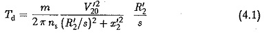
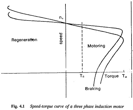
and the torque speed curve is as shown in Fig. 4.1. The slip for maximum torque is given by![]()
which is independent of stator voltage. However, this can be varied by variation in rotor resistance. The value of maximum torque is given by
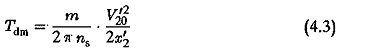
This also changes as the square of the applied voltage. If the voltage is reduced to 80% the maximum torque falls to 64%. The variation in applied voltage is achieved by means of a voltage controller.
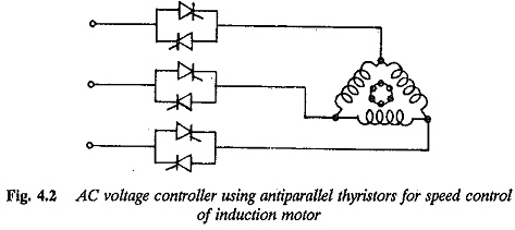
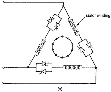
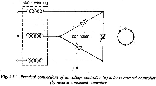
This method of controlling the speed of an induction motor is simple and economical. The stator voltage control is achieved by means of phase control of the antiparallel thyristors, connected as shown in Fig. 4.2. Figures 4.3(a) and (b) illustrate two practical connections of a voltage controller feeding an 3 Phase Induction Motor Construction. In the-connection of Fig. 4.2 the thyristors have to handle only phase current. The harmonic currents become higher. In Fig. 4.3 the harmonic penalty is rather more.
The stator voltage can be varied from zero to full value within the triggering angle range. The line side power factor is very poor because of harmonics and reactive power due to phase control.
When a cage induction motor is fed from a variable voltage supply for speed control the following observations may be made:
1.The torque speed curve beyond the maximum torque point has a negative shape. A stable operating point in this region is not possible for constant torque load.
2.The voltage controller must be capable of withstanding high starting The range of speed control is rather limited.
3.The motor power factor is poor.
To obviate the above difficulties the 3 Phase Induction Motor Construction must have a high resistance rotor. This makes the point of maximum torque shift towards s = 1, thereby reducing the unstable region of speed-torque curve. Due to increased rotor resistance the starting current decreases, the power factor improves and the range of speed control increases.
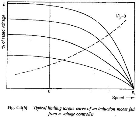
The method of speed control is therefore advantageous with a high resistance rotor. The speed-torque curves for this control are shown in Fig. 4.4(a). The current rating of the controller decides the possible torque at each speed. The limiting curve of the torque as a function of speed can be derived. Figure 4.4(b) shows this curve of limiting torque for design rating of the controller, which is three times the rated current of the motor. The current as a function of speed and stator voltage is depicted. During control, if the current value exceeds the limiting value, automatic current limit must be employed. By this the value of the firing angle gets adjusted until the permissible current flows.
Even though the method is simple and economical, the motor losses increase with increase in slip. The increase in the losses can be attributed to increase in the motor current due to drop in the air gap flux as well as to the high resistance of the rotor. The ratio r1/r′2 can be taken to be representative in deciding these losses because increase in the resistance is instrumental in limiting the current drawn. The efficiency of the motor can be approximately given by
![]()
where s is the slip of the motor.
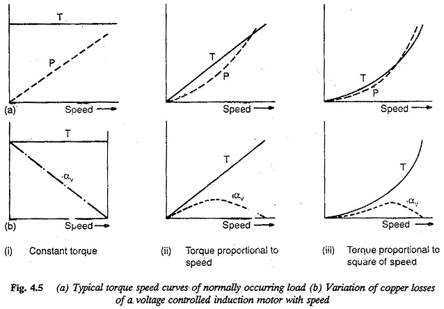
The type of load driven by the motor influences the current drawn and losses of the motor as the slip varies. The normally occurring loads are
1.constant torque loads
2.torque varying proportional to speed
3.torque varying proportional to the square of the speed
Let us consider that the torque speed characteristics of the load is given by a general equation
![]()
If the value of x = 0, it amounts of constant torque load. x > 0 for variable torque loads (Fig.4.5a).
The Rotor copper losses
![]()
where PD1 is the air gap power or power input to rotor.
But the slip of the motor
and the power input to the rotor
![]()
The maximum value of power transferred to rotor is
![]()
The copper losses when expressed as the ratio of PD1max we have
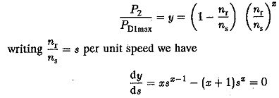
for the value of sat which y is maximum. The value of
![]()
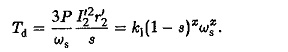
for maximum value of rotor copper loss. The maximum values of rotor copper losses are given by
![]()
As the value of x increases the value of ym decreases. The maximum value of rotor current and per unit speed at which it occurs can also be determined. We have
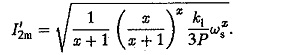
from which the rotor current
![]()
per unit speed for maximum value of rotor current is also
![]()
The maximum value of rotor current can be determined as
For special cases
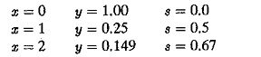
The variation of losses are shown in Fig. 4.5(b) for different types of loads. The constant torque loads are not favoured due to increase in the losses linearly with slip and becoming maximum at s = 1.0. This is obvious, from the variation of flux as the voltage is varied for speed control. To maintain constant torque the motor draws heavy current resulting in a poor torque/ampere, poor efficiency and poor power factor at low speeds.
When the torque varies in direct proportion to speed the copper losses has a maximum value of 25% of rated power at a speed of 0.5 ωs. For torques proportional to square of the speed, per unit speed at which copper losses are maximum is 2/3 and the maximum value of copper losses are 0.149 of rated power. The method of speed control can be advantageously employed for pump or blower type of loads where torque is proportional to square of the speed.
From the above discussion, this method of speed control is suitable only for the following cases:
1.For short time operations where the duration of speed control is defined.
2.For speed control of blowers or pumps having parabolic or cubic variations of torque with speed. This is not suitable for constant torque loads due to increased losses and heating.
3.For speed control of motor having poor efficiencies under normal operation.
The type of load (torque versus speed of the load) on the drive motor influences the losses in the motor. The non-sinusoidal input waveforms cause non-sinusoidal currents which increase the harmonic losses. Hence, the total losses increase particularly at low speeds and these losses cause a possible derating of the motor, or an over dimensioned motor must be used when this method is employed.
For blower type loads where T α N2 the maximum value of current occurs at a speed of 2/3 base speed. This current depends upon the full load slip of the motor. For large slip motors (high resistance rotors) the ratio of maximum to rated current decreases. For constant torque loads the power losses increase with reduction in speed and reaches a maximum value at zero speed itself. For loads having T α N the maximum occurs at 1/2 the base speed and the losses amount to 25% of the stator power.
The losses occurring in the motor are responsible for temperature rise of the motor. The losses must be kept within permissible value so that the motor operates always with permissible temperature rise. The different type of loads discussed have a tendency to increase the motor losses.
Further the waveform of the input voltage is distorted. The stator and rotor currents are non-sinusoidal with rich harmonic content. These harmonics cause additional losses. They can be taken as 50% of the rated copper losses.
The increase in the losses of the motor at large slips leads to a derating of the motor. A normal motor may be derated 5 to 6 times. If high resistance rotor is used the aerating factor decreases.
The total losses of the motor are
![]()
whete
fv takes care of increase in losses due to distortion and is normally taken as 1.5.
Pr is the rating of the motor
K1Pr is the total copper losses of the motor.
To maintain the permissible temperature rise, the permissible losses are
![]()
where
η is efficiency of the motor
αv is the ratio of losses at minimum speed to the losses at rated. speed.
PTvp rating of the motor.
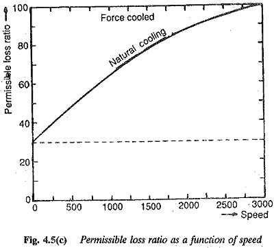
The factor αv depends upon the type of loading employed. For force cooled machines it is 1.0 and independent of speed. If the machine is self cooled it depends on speed. This value decreases as the lower limit of speed decreases. A typical characteristic for a two pole machine is shown in Fig. 4.5(c). The derating is also affected by the efficiency of the motor. As the efficiency decreases 1-η/η increases. For this type of speed control motors of large rotor 17 resistance are used. They have poor efficiency. Consequently the derating of the motor decreases.
The above discussion makes it clear that a given motor gets derated differently when it is driving different types of loads. In other words, the power required by the load is constant, the drive motor must be of different ratings for different types of torque-speed curves of the load, The following example illustrates this.